


1
Tools Needed:
NONE
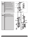
Thread the disconnect cable through the hole in the right hand
end bracket down through the long slot in the horizontal leg of
the horizontal angle. Remove all slack between opener and
right end bracket.
Routing Disconnect Cable
1
I-DRIVE DISCONNECT HANDLE
Supplemental insert
P.O. Box 67 Mt. Hope, OH 44660
GARAGE DOORS & OPENERS
© 2009 Wayne-Dalton Corp. Part No. 342295 NEW 5/29/2009
www.wayne-dalton.com
This supplemental installation instruction is to be used as a supplement to the main Installation Instruction and Owner’s Manual provided with the door. The instructions included in
this document are ONLY those which deviate from the standard installation. All WARNINGS and CAUTIONS listed in the main manual are applicable to this supplemental instruction as
well.
Disconnect
cable
Hole in
right
side of
end
bracket
Hole in right
end bracket
Torquemaster
®
Plus
Torquemaster
®
Slot in
horizontal angle
Disconnect
cable
6ft
6ft
Disconnect
handle and
mounting
bracket
Hole in right
end bracket
Disconnect
cable
Hole in
right
side of
end
bracket
Tools Needed:
Pencil
Tape Measure
Power Drill
1/8” Bit
7/16” Socket
Driver
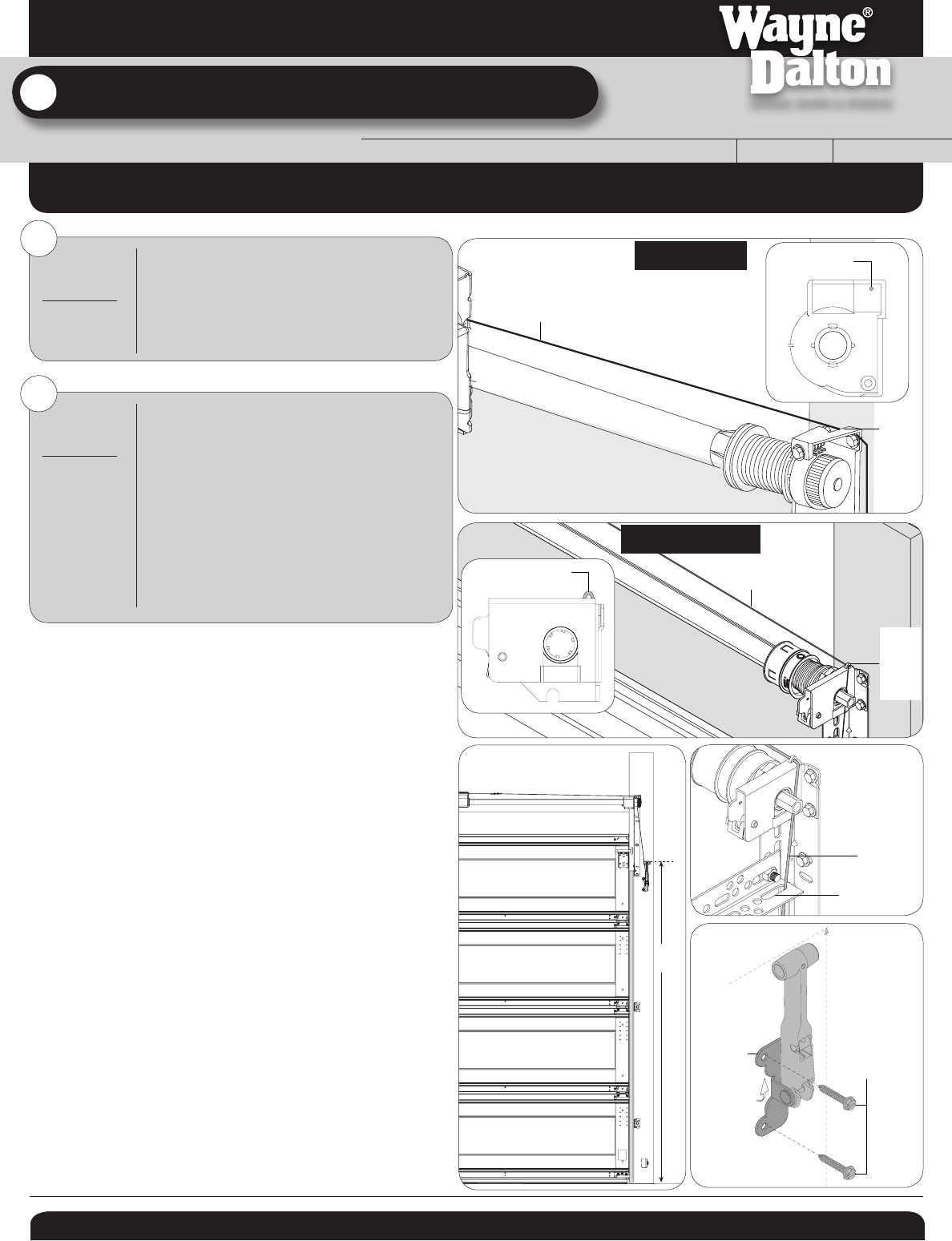
Mark a location on the right Jamb, 6 feet above the floor to
mount disconnect handle bracket.
Align top of the handle with the mark and mark location for
two lag screws.
Pilot drill lag screw location using 1/8” drill bit. Fasten bracket
to the jamb with (2) 1/4” x 1-1/2” lag screws.
Routing Disconnect Cable
2
(2) 1/4” X
1-1/2”
Lag screws