IMPORTANT! - This infrared safety sensor sends an invisible
beam of light from the sending unit to the receiving unit across
the door opening. The door opener will not operate until the
safety sensor is connected to the power unit and properly
aligned. If the invisible beam of light is misaligned or obstructed,
an open door cannot be closed by the transmitter or a momentary
activation of the wall mounted push button. However, the door
may be closed by holding your finger on the wall push button
(constant pressure) until the door travels to a fully closed
position.
WARNING
FAILURE TO MAKE ADJUSTMENTS
COULD RESULT IN SEVERE OR FATAL INJURY.
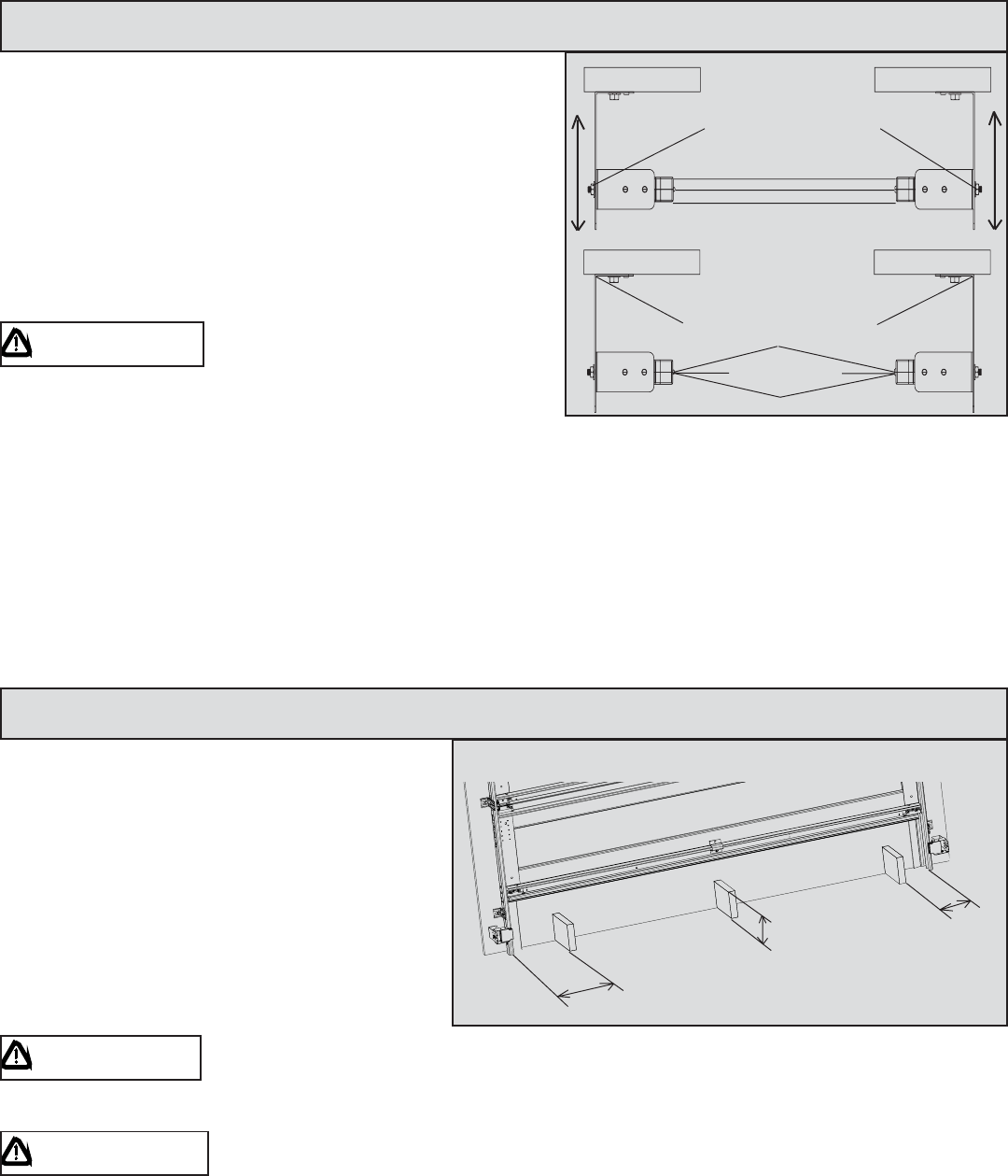
At this point you will be able to activate the opener; it will open, but will not close the door unless the sensors are
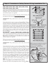
aligned and unobstructed. The safety sensors can be aligned by moving the sending and receiving units in or out
(see Fig. 5) until the alignment light on the receiving unit comes on. The 1/4-20 carriage bolt can be loosened to
move the unit in or out, as required. If you have difficulty aligning beams, check that both brackets are mounted at
the same height and remount if necessary. Additional minor adjustments can be made by lightly bending the
mounting brackets (see Fig. 6).Once the alignment light comes on, tighten all bolts and mounting screws. Finish
securing all wiring. Make sure not to break or pierce any of the wires. Loop and secure any extra wire. Now, using
the wall station’s up/down button, activate the opener and check that it will operate through full open and close
cycles.
6
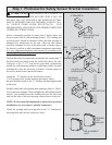
Starting with the door in the fully open position,
place a 6” high object on the floor progressively
one foot from the left side of the door, center of
door and one foot from the right side of the door.
(Fig. 7) In each position, activation of the opener
with the wallstation up/down button should cause
the door to move no more than one foot, stop and
then reverse to fully open position. The same 6”
high object when placed on the floor, while door is
closing, should also cause the door to reverse.
WARNING WHEN PERFORMING THIS PART OF THE TEST, DO NOT PLACE YOURSELF
UNDER DESCENDING DOOR, OR SEVERE OR FATAL INJURY MAY RESULT.
WARNING
IF THE OPENER DOES NOT RESPOND PROPERLY, OR FAILS THESE TEST,
HAVE A QUALIFIED SERVICE PERSON MAKE NECESSARY ADJUSTMENTS/REPAIRS.
FAILURE
TO MAKE ADJUSTMENTS COULD RESULT IN SEVERE OR FATAL INJURY.
Step 4: Photoelectric Obstruction Sensing Test
Step 3: Photoelectric Safety Sensor Alignment
12”
6”
12”
FIG.5
FIG.6
Top View
Align In Center
(In/Out)
1/4-20 Carriage bolts
IN
OUT
IN
OUT
For this adjustment bend
bracket at wall mount
Top view
Align in Center
FIG. 7


