


General Information
Sewage Pump Systems:
Simplex System
A simplex system consists of one pump,
its control switch, and one basin. It is
used in applications where less than
six toilets (units) are discharged into
a basin. The simplex unit is generally
operated with a contactor to turn
the pump ON and OFF. The contactor
is activated by a single pole float
switch. The float switch is a wide-angle
differential switch that rises with the
liquid level and turns the pump ON.
As the liquid level decreases, the float
lowers and turns the pump OFF. The
switch differential is 120º.
Sewage Pump Systems:
Duplex System
A duplex system is used in applications
where more than six toilets (units) are
discharged into a basin. However, each
pump should be sized to handle the entire
flow in case one pump fails. The duplex
unit is controlled by a NEMA 1 control
panel that has an automatic alternator,
run lights, hand-off-auto switches, and
an alarm bell. The duplex control panel
is supplied with three float switches. The
floats are to be positioned so that the
lower float turns the pumps OFF. The
second float alternates turning first one
pump ON and then the other pump ON.
The third float will turn BOTH pumps ON
in case one pump cannot handle the flow.
The third float will also sound the alarm
(which remains on until the system is reset).
Functionally, the liquid in the basin rises
and trips the first float, but the pumps do
not turn ON. As the liquid level rises, it
trips the second float, activating one of the
pumps. Once the liquid level recedes and
no longer trips the second float, the pump
will turn OFF. If the second float is tripped
again, the other pump will turn ON.
If for some reason the liquid level
increases past the second float and trips
the third float, both pumps turn ON and
trips the alarm.
Under normal circumstances, the first
pump will handle the flow after the
second float is tripped. In those cases,
the liquid level will recede until it drops
the lower float. This action turns the
pump OFF. The next time that the liquid
level rises, the other pump turns ON. This
alternates the pumps; this prevents lock-
up and extends the lifer of both pumps.
Available Controls
For 115 volt only, a wide angle float
switch can be supplied with a plug-thru
series plug.
For 230 volt Simplex units, a NEMA 1
Simplex Controller with a hand-off-auto
switch and run light can be supplied.
This is supplied with a wide-angle
switch for automatic operation.
For 230 volt Duplex units, a NEMA 1
control panel can be supplied with
a hand-off-auto switches, run lights,
pump alternator, and an alarm bell.
This is supplied with a three float switch
system for automatic operation.
2
Operating Instructions and Parts Manual
www.waynepumps.com
Installation
Always
disconnect
the power source before
attempting to install, service,
relocate or maintain the pump.
Never touch sump pump, pump motor,
water or discharge piping when pump is
connected to electrical power. Never handle
a pump or pump motor with wet hands or
when standing on wet or damp surface or
in water. Fatal electrical shock could occur.
Some models of this product include
a grounded plug for quick installation
anywhere a grounded outlet is
accessible. Some models must be
incorporated into the building’s
electrical system. Models without plugs
must be connected to a grounded
circuit. The circuit should be equipped
with a ground fault interrupter device.
All models without plug-in power cords
systems must be installed by a qualified
electrician. All models with a plug-in
power cords system should still have a
qualified electrician inspect the outlet
being used to ensure proper wiring.
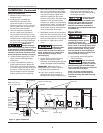
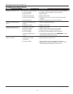
The control switch is a wide-angle
system which prevents short cycling of
the pump motor and the consequential
problems that short cycling can cause.
The switch can be mounted on the
discharge pipe (just above the pump
discharge flange). See illustrations for
switch mounting arrangements.
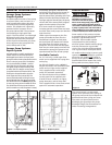
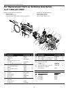
Figure 1 - Simplex System Figure 2 - Duplex System
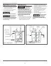
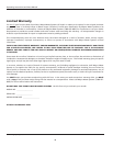
Grounding
Blade
Grounded
Outlet
Power
Cord
Switch
Cord
TEST
RESET
Figure 3