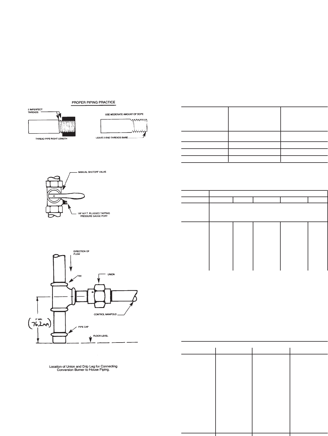
8
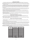
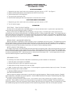
After the piping and meter have been checked completely, purge the system of air. Do not bleed the air inside the furnace.
Be sure to relight all the gas pilots on other appliances.
PURGING
After the piping has been checked, all piping and appliances receiving gas through the meter shall be fully purged. A
suggested method for purging th gas line to the burner is to disconnect the pilot line at the outlet o the pilot valve. Under no
circumstances shall th line be purged into the combustion chamber.
After th e gad line to the conversion burner has been fully purged and the pilot line reconnected, the gas supply at other pilot
burners located on other gas appliances which were extinguished as the result of interrupted service shall be reignited.
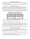
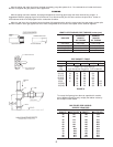
LENGTH OF STANDARD PIPE THREADS inches (mm)
EFFECTIVE OVERALL
PIPE SIZE LENGTH LENGTH
OF THREAD OF THREAD
3/8 (9.525) 3/8 (9.525) 9/16 (14.29)
1/2 (12.7) 1/2 (12.7) 3/4 (19.05)
3/4 (19.05) 1/2 - 9/16 (14.29) 13/16 (20.64)
1 (25.4) 9/16 (14.29) 1 (25.4)
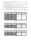
PIPE CAPACITY TABLE
Nominal Diameter of Pipe in Inches
3/4 (19.05) 1(25.4) 1-1/4 (31.75) 1-1/2 (38.1) 2 (50.8)
Length
of Pipe Capacity - Cu, Ft. Per Hr. with a 0.6
in Feet Sp. Gr. Gas and Press. Drop of 0.3 In. (74.72 Pa) Water Col.
15 (4.572) 172 345 750
30 (9.144) 120 241 535 850
45 (13.72) 99 199 435 700
60 (18.29) 86 173 380 610
75 (22.86) 77 155 345 545
105 (32) 65 131 285 450 920
120 (36.58) 120 270 420 860
180 (54.86) 100 225 350 720
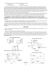
FIGURE 8
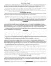
To convert the figures given above to capacities for another
gas of different specific gravity, multiply the tabular values by
the multiplier shown below.
MULTIPLIER FOR VARIOUS
SPECIFIC GRAVITIES
SPECIFIC SPECIFIC
GRAVITY MULTIPLIER GRAVITY MULTIPLIER
.35 1.31 1.00 .775
.40 1.23 1.10 .740
.45 1.16 1.20 .707
.50 1.10 1.30 .680
.55 1.04 1.40 .655
.60 1.00 1.50 .633
.65 .962 1.60 .612
.70 .926 1.70 .594
.75 .895 1.80 .577
.80 .867 1.90 .565
.90 .817 2.10 .535


