


The pump motor is
equipped with
automatic resetting thermal protector
and may restart unexpectedly.
Protector tripping is an indication of
motor overloading as a result of
operating the pump at low heads (low
discharge restriction), excessively high
or low voltage, inadequate wiring,
incorrect motor conditions, or a
defective motor or pump.
14. This pump is designed to transfer water
in cycles. Using this pump in a
continuous duty application by ma nip u -
lat ing the switch to stay on, will affect
the per for mance and the life of the
product.
15. Protect electrical cord from sharp
objects, hot sur fac es, oil, and chemicals.
Avoid kinking the cord. Re place or repair
damaged or worn cords im me di ate ly.
Use wire of adequate size to minimize
voltage drop at the motor.
16. Do not handle a pump or pump motor
with wet hands or when standing on a
wet or damp surface, or in water.
17. Do not hang this product by the carry
handle. Sewage pumps should be set
firmly on their legs and supported by
rigid piping. This eliminates twisting and
damage during pump operation.
18. Do not use an extension cord.
Do not walk on wet area
until all power has been
turned off. If the shut-off
box is in basement, call the
electric company to shut-off service to
the house, or call the local fire
department for instructions. Remove
pump and repair or replace. Failure to
follow this warning can result in fatal
electrical shock.
Risk of electric shock!
Never connect the green (or
green and yellow) wire to a
live terminal!
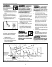
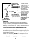
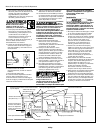
11. This equipment is only for use on 120
volt (single-phase) and is equipped with
an ap proved 3-con duc tor cord and 3-
prong, grounding-type plug as shown in
Fig ure 1.
To reduce the risk of electric shock, the
motor must be securely and adequately
grounded. This can be ac com plished by the
following:
a. Inserting plug directly into a properly
installed and grounded 3-prong,
grounding-type re cep ta cle (as shown in
Figure 1).
b. Permanently wiring the unit with a
grounded, metal raceway system.
c. Other suitable means.
Where a 2-prong wall receptacle is
encountered, it must be replaced with a
properly grounded 3-prong re cep ta cle
installed in accordance with the NEC and
local codes and ordinances.
12. All wiring should be performed by a
qualified elec tri cian.
13. Always connect this product to a
grounded outlet equipped with a
Ground Fault Circuit Interrupter (GFCI)
device. Con sult a local electrician for
installation and availability.
2
Operating Instructions and Parts Manual
Installation
In any installation
where property
damage and/or personal injury might
result from an inoperative or leaking
pump due to power outages, discharge
line blockage or any other reason, use
a backup system(s).
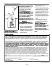
1. Thread the discharge pipe or pipe nipple
into the dis charge connection.
2. If a check valve is used in a solids
handling system mount the check valve
in a horizontal position or at a 45° angle
with the valve pivot on top. In a vertical
position, solids will tend to lodge on the
valve flapper and can prevent it from
opening.
3. Drill a 1/16" hole in the discharge pipe
ap prox i mate ly 1" to 2” above the pump
discharge when a check valve is used.
The hole prevents air locking of the
pump at the initial start-up and if it
should lose prime.
4. A gate valve should be installed in the
system after the check valve. This gate
valve should be a full port valve which
will pass 2" solids or as required by state
and local codes. This gate valve permits
removal of the pump and/or check valve
for servicing.
5. A union should be installed between the
check valve and the pump so the pump
can be removed with least disturbance
of the piping.
6. When a tether switch is used, rigid dis -
charge pipe is required. If the pump is
allowed to move, the tether switch
could be re strict ed by the basin wall,
pre vent ing the pump from operating.
Before removing
pump from basin
for service, always disconnect electrical
power to pump and control switch. For
any work on pump or switch, ALWAYS
unplug the power cord. Do not just turn
off circuit break er or unscrew fuse.
Grounding
Blade
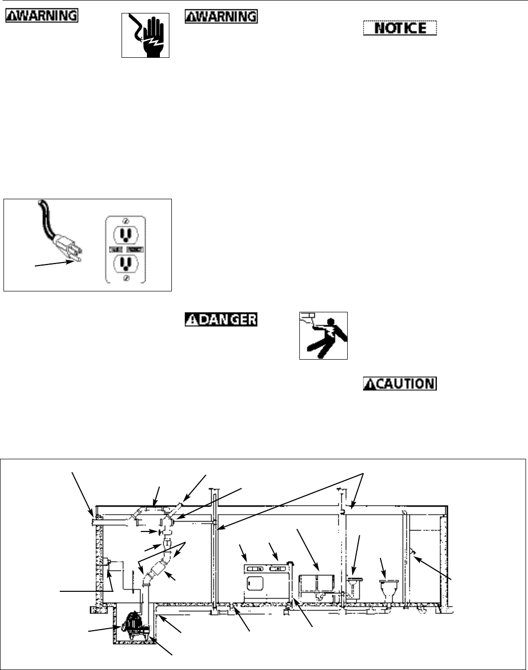
Figure 1
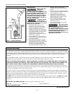
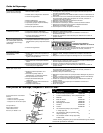
Main waste line to sewer or septic tank
Upper level drainage
Three prong
grounded outlet
equipped with a
ground fault
interruptor
2” Discharge pipe
Float switch
Sewage pump passes 2” dia. solids
Cleanout
Vent pipe
2” Gate
Valve
Union
2” Check
Valve
45
o
Elbow
Laundry tubs
Washer
Dryer
Floor drain
Washer drain
Lavatory
Toilet
Shower
Flange
Figure 2 - Typical Installation
www.waynepumps.com