


4
www.waynepumps.com
Installation (Continued)
DRIVEN WELL
• Drive the point several feet below
the water table.
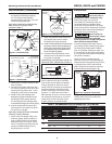
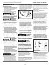
NOTE: A packer type foot valve can
be installed in the well (Figure 3,
Illustration B). This type of foot valve
allows the well to be filled with water
when priming and makes the inlet pipe
much easier to test for leaks. Follow
the manufacturer’s instructions when
installing the packer type foot valve.
As an alternative, an in-line check valve
can be used with a driven well (Figure
3, Illustration C). The pipe between the
check valve and the water level will
always be under a vacuum.
Leaking joints or couplings will allow
air to leak into the pipe and cause
abnormal pump operation. Make sure
to use pipe joint compound on all male
pipe threads.
DUG WELL, CISTERN, LAKE AND SPRING
INSTALLATION (FIGURE 17)
• Install a foot valve on inlet pipe and
lower into water.
The foot valve
should be at least 18
in. from the bottom of the well or sand
or sediment could be drawn into the
system.
NOTE: When a lake is used as a water
supply, make sure the inlet pipe is deep
enough to be submerged at all times.
Protect the pipe from damage from
swimmers and boats.
Slope the horizontal piping upward
toward the pump to prevent trapping
air. The pipe must be removed during
winter months or protected against
freezing.
Protect the pipe from damage from
swimmers and boats.
Install a screen
around the inlet
pipe to prevent the entrapment of
swimmers.
DEEP WELL INSTALLATION
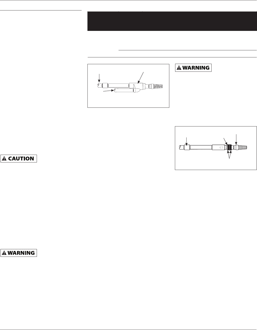
DRILLED WELL (4 IN. OR LARGER) WITH
TWO PIPE JET (FIGURES 17 AND 4)
1. Assemble a 1-1/4 in. foot valve (not
included) to the jet body. A 1-1/4 in.
coupling is required to connect the
larger pipe to the jet assembly.
2. Connect the 1 in. pipe threads into
the smaller opening in the jet body.
3. Lower the jet into the well. Add pipe
as needed. Be sure to use pipe joint
compound on all male threads.
4. Position the jet 10 - 20 feet below
the lowest anticipated water level,
but never closer than 5 feet from the
bottom of the well, if possible.
5. Install a well seal to support the pipe
and prevent surface water and other
contaminants from entering the
well.
6. Install the horizontal pipe from
the well to the pump. Piping from
the vertical well pipe to the pump
should never be smaller than the
well pipes.
7. Slope both pipes upward toward
the pump to prevent trapping air. If
the horizontal distance exceeds 25
feet, see Chart 2 (on page 5) for the
recommended pipe sizes.
DUG WELL, CISTERN, LAKE AND SPRING
WITH TWO PIPE JET (FIGURE 17)
1. Install a 1-1/4 in. foot valve (not
included) to the jet body. A 1-1/4 in.
coupling is required to connect the
larger pipe to the jet assembly.
2. Connect the 1 in. pipe threads into
the smaller opening in the jet body.
3. Lower the jet into the water below
the lowest anticipated water level,
but never closer than 18 in. from
the bottom. Sand or debris may be
drawn into the system if the jet is
too close to the bottom.
4. Provide protection for the jet and
pipes against damage from boats
or swimmers if a lake is used for the
water supply.
Install a screen
around the inlet
pipe to prevent the entrapment of
swimmers.
5. Slope the horizontal pipes upward
toward the pump to prevent
trapping air. If horizontal distance
exceeds 25 feet, see Chart 2 for
recommended pipe sizes.
DRILLED WELL (2 IN.) WITH SINGLE PIPE
PACKER (FIGURES 17 AND 5)
NOTE: Single pipe packer jets rely on
the space between single pipe and
inside of well casing for return water to
operate jet. Two inch installations must
use 1-1/4 in. galvanized steel pipe with
special turned couplings (1-13/16 in.
O.D.) to avoid restricting flow of return
water back to jet.
1. Assemble the foot valve and packer
to the jet body.
2. Lubricate the rubber cups with
petroleum jelly.
3. Attach the first section of pipe and
lower jet into well.
4. Add pipe until the jet is positioned 5 -
15 feet below the lowest anticipated
water level. The jet should never be
closer than 5 feet from the bottom of
the well or sand and sediment may
be drawn into the system.
5. With the jet in position, fill the pipes
with water to make sure the rubber
cups are sealed against inside of the
well casing. It may be necessary to
move the jet up and down to seat
the cups.
6. Install the casing adapter and the
horizontal pipes.
Operating Instructions & Parts Manual
CWS50, CWS75 and CWS100
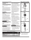
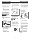
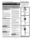
Figure 4 - Two Pipe Jet
Jet Body
Foot Valve
1-1/4 in. Pipe
1 in.
Pipe
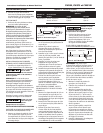
Figure 5 - Single Pipe Jet
Packer
Foot Valve
1-1/4 in. Pipe
Cups
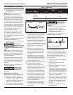
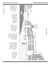
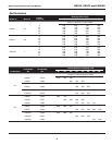
CHART 2 - PIPE SIZING
Pump Model
Pump
Opening
Horizontal Distance
(Feet)
0-25 26-100
Deep Well Inlet:
Suction
1-1/4 in. 1-1/2 in.
Inlet: Drive 1 in. 1-1/4 in.
Outlet 3/4 in. 1 in.