


3
WSA120
www.waynepumps.com
During a flood emergency the warning
beeper volume can be reduced or
turned off completely. The mute button
(Fig. 10) can be used to temporarily
silence the alarm. Remember to turn
the beeper back on after the issue in
the sump pit has been resolved.
OPTIONAL: ADDING ADDITIONAL
TRANSMITTERS
The receiver is capable of monitoring up
to four different sump pits. Transmitters
for homes with multiple sump pits may
be purchased separately. Additional
programming steps are required for
multiple monitoring stations.
For additional transmitters call
WAYNE pumps at 1-800-237-0987
to order part number: 66902-001
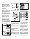
CODE CONNECTORS
The code connectors consist of
6 movable circuits on both the
transmitter and receiver. The code
connectors are required for the sensor
to communicate with the receiver.
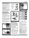
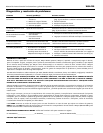
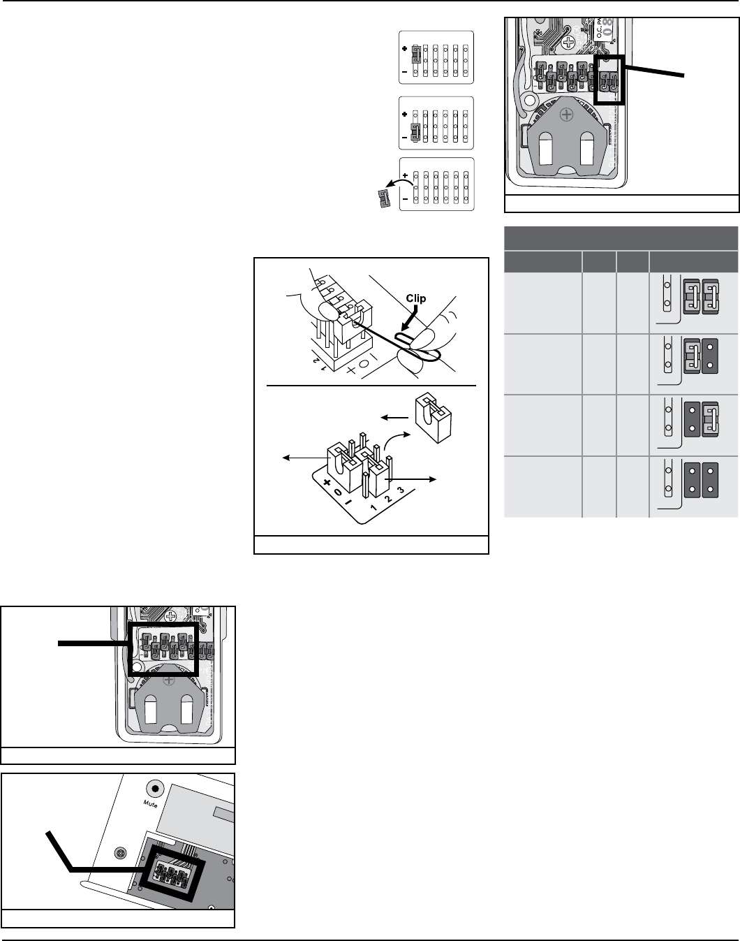
Openthetopcoverofthesensor
(Fig. 9) and the back cover of the
receiver (Fig. 10) for access to the
codeconnectors.Bothsetsofcode
connectors must match for the Wireless
Alarm to work properly.
These code connectors can be set at
anyrandompattern.Besuretousethe
same pattern on the receiver that is
used on the transmitter.
Operation (continued)
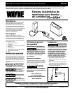
Each circuit can be positioned 3 ways.
1. Positive (+): circuit
connects the "0"
prong and the "+"
prong.
2. Negative (-): circuit
connects the "0"
prong and the "-"
prong.
3.Zero(0):circuitis
removed
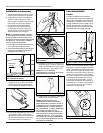
Use the clip provided (Fig. 11) to set the
code connectors properly.
NOTE: IF YOU EXPERIENCE INTERFER-
ENCE FROM A NEARBY SYSTEM, WHICH
COULD ACCIDENTALLY TRIGGER YOUR
SYSTEM, PLEASE CHANGE THE CODE
SETTINGS ON THE SENSOR AND RECEIV-
ER. THE CODE SETTING ON THE SENSOR
AND RECEIVER MUST MATCH AFTER
CHANGING THE CODE SETTING.
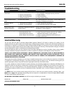
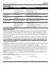
ZONE CONNECTORS
The receiver can work with up to 4 dif-
ferent sensors. There are 4 different
lights on the receiver that correspond
to each zone.
Onthetransmitter,thereare2connec-
tors that determine zone numbers 1,
2, 3 and 4. These 2 connectors can be
found by opening the top plastic cover,
near the code connectors with marking
“A”&“B”(Fig.12).
Please follow table A to set the zone.
•Apositivesign(+)meansthe
connector is placed on the posts.
•Negativesign(–)meansthe
connector is removed from the posts.
After setting up all the connectors, both
units are ready to be powered up.
Plug in the adapter to the receiver, the
green LED will start flashing, indicating
the receiver unit is powered up but no
sensor is detected.
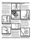
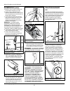
Remove the top cover of the sensor
andinsertthe3Vlithiumbatterytothe
transmitter (Fig. 5).
After inserting the battery to the water
sensor, the receiver will beep and the
green LED on the receiver will stop flash-
ing and stay on.
NOTE: IF THE LIGHT CONTINUEES TO
FLASH, LIFT UP THE FLOAT TO RESET
THE SYSTEM
NOTE: ONLY THE SENSOR PORTION OF
THE WATER SENSOR IS WATERPROOF,
THE TRANSMITTER PORTION SHOULD
NEVER BE SUBMERGED IN WATER.
Put the top cover back on and you are
now ready to mount the water sensor.
1
2
3
4
5
6
Figure 12: Zone connectors (Transmitter)
ZONE
CONNECTORS
1
2
3
4
5
6
Figure 9: Code Connectors (Transmitter)
CODE
CONNECTORS
Figure 11: Connection Removal
1
2
3
4
5
6
Figure 10: Code Connectors (Receiver)
CODE
CONNECTORS
TABLE A
ZONE A B ex am pl e
zone 1
+ +
zone 2
+ –
zone 3
– +
zone 4
– –
1
2
3
4
5
6
0
1
2
3
4
5
6
0
1
2
3
4
5
6
0
1
2
3
4
5
6
0
1
2
3
4
5
6
0
1
2
3
4
5
6
0
1
2
3
4
5
6
0
1
2
3
4
5
6
0
1
2
3
4
5
6
0
1
2
3
4
5
6
0
1
2
3
4
5
6
0
1
2
3
4
5
6
0
1
2
3
4
5
6
0
1
2
3
4
5
6
0
1
2
3
4
5
6
0
1
2
3
4
5
6
0
1
2
3
4
5
6
0
1
2
3
4
5
6
0
1
2
3
4
5
6
0
1
2
3
4
5
6
0
1
2
3
4
5
6
0
1
2
3
4
5
6
0
1
2
3
4
5
6
0
1
2
3
4
5
6
0
1
2
3
4
5
6
0
A
A
A
A
B
B
B
B