


3
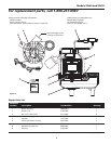
Models SEL40 and SEL50
www.waynepumps.com
availability.
General Safety Information
(Continued)
The pump motor
is equipped with
automatic resetting thermal protector
and may restart unexpectedly. Protector
tripping is an indication of motor
overloading as a result of operating
the pump at low heads (low discharge
restriction), excessively high or low
voltage, inadequate wiring, incorrect
motor conditions, or a defective motor
or pump.
14. This pump is designed to transfer
water in cycles. Using this pump in
a continuous duty application by
ma nip u lat ing the switch to stay on,
will affect the per for mance and the
life of the product.
15. Protect electrical cord from sharp
objects, hot sur fac es, oil, and
chemicals. Avoid kinking the cord.
Re place or repair damaged or worn
cords im me di ate ly. Use wire of
adequate size to minimize voltage
drop at the motor.
16. Do not handle a pump or pump
motor with wet hands or when
standing on a wet or damp surface,
or in water.
17. Do not hang this product by the
carry handle. Sewage pumps
should be set firmly on their legs
and supported by rigid piping. This
eliminates twisting and damage
during pump operation.
18. Do not use an
extension cord.
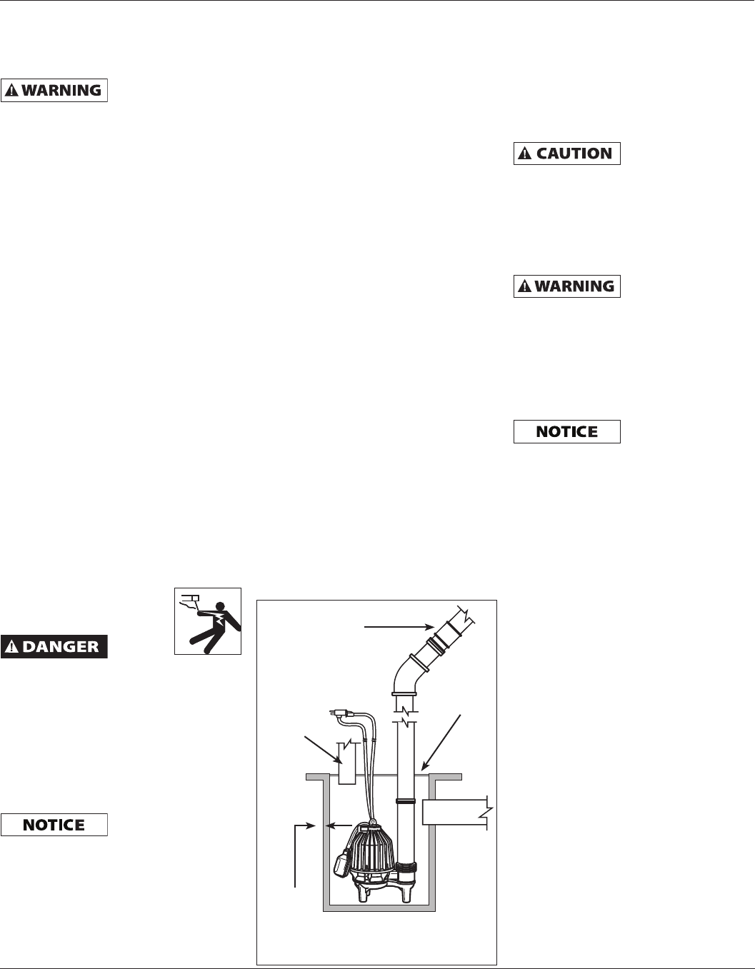
Do not
walk on
wet area until all power has been
turned off. If the shut-off box is in
basement, call the electric company to
shut-off service to the house, or call the
local fire department for instructions.
Remove pump and repair or replace.
Failure to follow this warning can result
in fatal electrical shock.
Installation
In any installation
where property
damage and/or personal injury might
result from an inoperative or leaking
pump due to power outages, discharge
line blockage or any other reason, use a
backup system(s).
1. Thread the discharge pipe or
pipe nipple into the dis charge
connection.
2. If a check valve is used in a solids
handling system mount the check
valve in a horizontal position or at
a 45º angle with the valve pivot on
top. In a vertical position, solids will
tend to lodge on the valve flapper
and can prevent it from opening.
3. Drill a 1/8 inch hole in the discharge
pipe ap prox i mate ly 1 inch to 2 inch
above the pump discharge when
a check valve is used. The hole
prevents air locking of the pump at
the initial start-up and if it should
lose prime.
4. A gate valve should be installed in
the system after the check valve.
This gate valve should be a full port
valve which will pass 2 inch solids or
as required by state and local codes.
This gate valve permits removal of
the pump and/or check valve for
servicing.
5. A union should be installed between
the check valve and the pump so the
pump can be removed with least
disturbance of the piping.
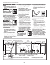
6. The pump has a detachable tether
switch with a piggyback plug (see
Figure 3). The length of the tether
(distance of cord from float to
clamp) should not be set shorter
than 3-1/4 inches and should not
be used in a basin smaller than
14 inches in diameter. If using a
differential other than the factory
setting, be sure when the pump
shuts off at least 4 inch of fluid is left
in the basin so the impeller remains
submerged.
7. When a tether switch is used, rigid
dis charge pipe is required. If the
pump is allowed to move, the
tether switch could be re strict ed
by the basin wall, pre vent ing the
pump from operating.
Before removing
pump from basin
for service, always disconnect electrical
power to pump and control switch. For
any work on pump or switch, ALWAYS
unplug the power cord. Do not just turn
off circuit break er or unscrew fuse.
Maintenance
Make certain that
the pump is
unplugged before attempting to service
or remove any component. This pump is
assembled in the factory using special
equipment; therefore only authorized
service dealers or qualified electricians
should attempt to repair this unit.
Improper repair can cause an electrical
shock hazard.
The pump contains
oil that may be
under pressure because of heat. Let the
pump cool for a minimum of two hours
before servicing this unit.
1. Disassembly of the motor prior to
expiration of war ran ty will void
the warranty. It might also cause
internal leakage and damage to the
unit. If repairs are required, return
the pump to the dealer from whom
it was pur chased or call 1-800-237-
0987. If motor is ever disassembled
the o-rings must be replaced. Care
must be taken to ensure that all
seals do not leak.
2. After the basin cover is removed
and necessary dis charge piping
disconnected, lift pump from basin.
3. Pump should be checked on a
regular basis for proper op er a-
tion. If anything has changed since
unit was new, the unit should be
removed and repaired or replaced.
Only qualified electricians or service
peo ple should at tempt to repair
this unit. Improper repair and/or
assembly can cause an electrical
shock hazard.
4. Place the pump in a suitable area
where it can be cleaned thoroughly.
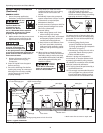
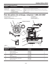
Check valve 45º
Vent
Inlet
Gasket
1/2 inch
Min.
Clearance
Basin
Figure 3 - Prefabricated Basins