3
PC1 and PC2 Series
www.waynepumps.com
Operation (Continued)
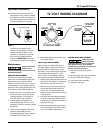
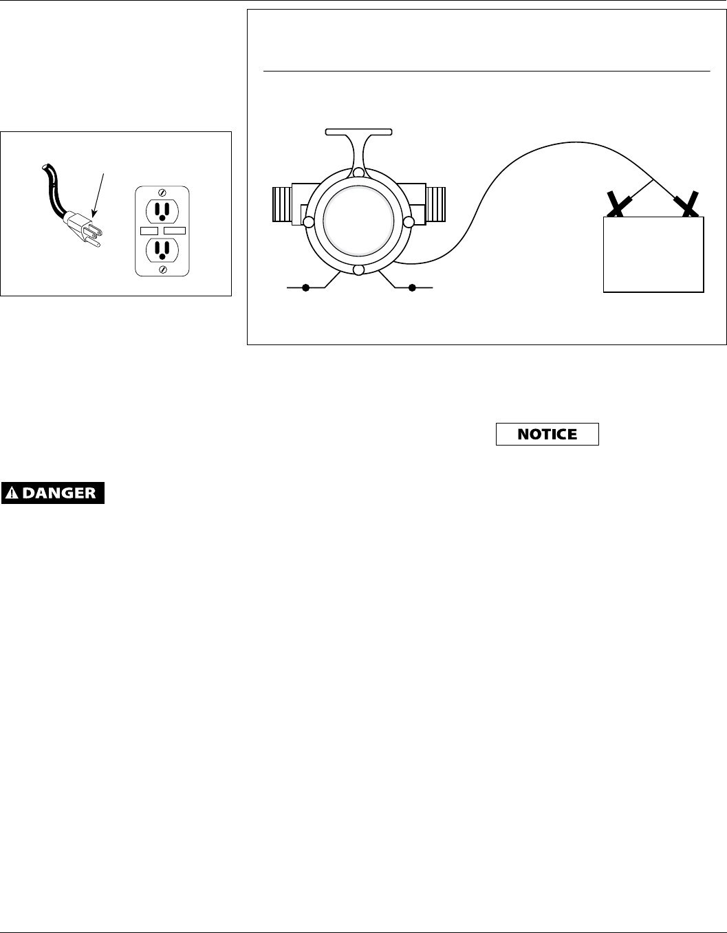
4. Connect pump to power source,
with pump in a dry location. Model
PC1: Motor must be connected to a
fully charged automotive tractor or
marine type battery to operate.
Connect the red clamp to the
positive (+) type battery terminal.
Connect the black clamp to the
negative (-) type battery terminal.
See 12V wiring diagram below
(Figure 2).
Model PC2: Plug into a
3-prong ground-type AC receptacle.
Maintenance
Always disconnect
power source
before attempting to install, service, or
maintain the pump.
IMPELLER REPLACEMENT
These parts are designed to handle
most clear, nonflammable liquids with
slight amounts of abrasives. When
impeller vanes become worn from use,
or damaged due to pumping abrasive
liquids or trash, pump performance will
be reduced or prevented altogether.
1. Remove the four cover plate screws
holding motor housing and pump
housing together. Cover plate is
now free and can be removed.
2. Inspect gasket and impeller for
wear and damage. If there is any
evidence of wear or damage, replace
the part(s).
3. Lubricate new impeller with white
grease or lightweight oil and
reinstall by aligning flat on impeller
hub with flat on motor shaft.
4. Reassemble gasket, cover plate, and
cover plate screws.
SHAFT SEAL REPLACEMENT
Motor shafts are sealed with factory
pre-lubricated lip-type seals which are
good for the life of the pump. If the
seal leaks, it is usually because the pump
has handled abrasive liquids. If the
motor shaft is scored (deep grooves),
the complete pump must be replaced.
1. Remove and inspect impeller parts as
specified in the impeller replacement
instructions. Replace worn parts.
2. Remove two pump body mounting
screws and slide pump body from
motor. Pry out seal retaining ring
and push worn shaft seal from inside
of pump body.
3. Lubricate new seal with lightweight
oil, push it into pump body with lip
facing away from motor, and push in
seal retaining ring.
4. Reassemble pump body onto motor
with mounting screws. Follow steps
3 and 4 in Impeller Replacement.
MOTOR BRUSH REPLACEMENT
Brushes for this
pump should be
inspected after 75 hours of operation
and replace if worn. They must be
replaced every 100 hours of operation.
Service one brush at a time.
1) Disconnect pump from power
supply.
2) Remove brush caps with screwdriver.
3) Remove old brush assembly.
4) Insert new brush assembly.
5) Replace brush caps.
TEST
RESET
Grounding Plug
Figure 1
12 VOLT WIRING DIAGRAM
RED CLAMP
TO POSITIVE
TERMINAL
BLACK CLAMP
TO NEGATIVE
TERMINAL
POS
+
12 VOLT DC
BATTERY
-
NEG
12 VOLT DC PUMP
INLETOUTLET
Figure 2


