


INSTALLATION MANUAL
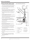
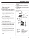
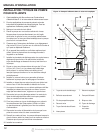
8. Drill 1/8 in. “weep” hole in the discharge pipe 1 in. above
the pump discharge. Water stream will be visible from
the how when the pump is running. The hole must be
cleaned periodically.
9. Install a union to allow for easy removal of the pump for
cleaning or service.
10. Install a check valve (required) to prevent back-fl ow. The
check valve may be positioned just above the basin to
allow easy removal of the pump for cleaning and service.
11. Install a gate valve or ball valve if required by local,
regional or state code.
12. Secure cords to discharge pipe to prevent possible
switch entanglement. Use cable or zip ties to secure the
power cords.
13. Connect pump power supply cord to a properly
grounded receptacle.
14. Fill the basin with water. The pump will start when the
water level has reached the switch-on level.
15. The pump will stop when the water level has reached the
switch-off level.
16. Verify the switch is operating with out any obstruction
from the pump, piping and basin.
17. Fill the basin with water again. While the pump is
draining the basin, verify the discharge pipe is carrying
the water to a point at least 3 ft. away from the
foundation. If the discharge line is exposed to freezing
temperatures, the pipe must be positions in a downward
slope away from the foundation so any remaining water
will drain away and not freeze.
3
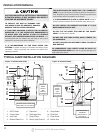
TYPICAL SUMP INSTALLATION
1. This installation must be in accordance with the National
Electric Code and all applicable local codes and
ordinances.
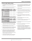
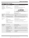
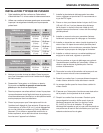
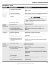
2. Use a basin that is large enough to accommodate the pump.
The minimum requirements for the sump pumps are:
CHART — A
Switch Type
A
Minimum
Basin Diameter
B
Minimum
Basin Height
Submersible Sumps
Tether Float Switch 14 in. 22 in.
Diaphragm Switch 14 in. 22 in.
Vertical Float Switch 11 in. 22 in.
iSwitch Technology Switch 11 in. 22 in.
CHART — B
Switch Type
A
Minimum
Basin Diameter
B
Maximum
Basin Height
Pedestal Float Switch
(Figure 2)
14 in. 22 in.
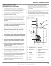
3. Clean the basin of all debris. Position pump so the switch
is away from the inlet and is clear from incoming water.
4. Assemble switch or fl oat if needed. Refer to warranty
and service parts sheet for specifi c directions.
5. Set the pump on a solid, level surface. Do not place pump
directly on clay, earth, gravel or sand. A brick or block may
be installed under the pump to provide a solid base.
6. Position pump so the switch is away from the inlet so
switch is clear from incoming water. Verify the switch
has at least 1 in. clearance to the side wall of the
basin and is free to move throughout its movement. If
optional control device or fl oat is used, follow mounting
instruction supplied with device or fl oat.
7. Install discharge plumbing according to local, regional
and state codes. Rigid PVC pipe is recommended.
Printed on 100% Recycled Paper