


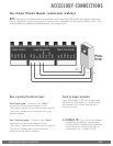
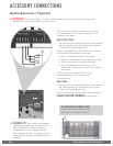
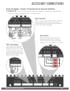

VIKING TECHNICAL SUPPORT 1.800.908.0884
36
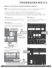
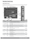
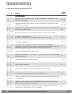
LED References
In addition to the LCD Display, the control board LEDs monitor the various circuits of the
control board. Use the table below to identify the corresponding “TS Ref#” and refer to
page 38-41 for further troubleshooting.
TROUBLESHOOTING
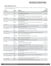
# LED Status Meaning
Page 41
TS Ref#(s)
1 “Magnetic
Lock Relay”
OFF At Closed Limit and Magnetic Lock Relay state is closed across “COM” &
“N.C.”. (pg 34). Gate should be at the Close Limit.
SOLID Not at Closed Limit and Magnetic Lock Relay state is closed across “COM” &
“N.O.”. (pg 34). Gate should not be at the Close Limit
2 “Check Motor” OFF Normal Condition.
SOLID The control board is sending power to the motor but the circuit is open.
7, 8
3 “Battery Low” OFF Normal Condition.
SOLID Batteries are low. Check power supply to the operator. (pgs 18-19).
1, 2
FLASHING Batteries critically low. Check power supply to the operator. (pgs 18-19).
1, 2
4 “POWER” SOLID Normal Condition.
FLASHING Operator is running on batteries only (pgs 18-19).
1, 2
OFF No power to control board.
1, 2, 4, 5
5 “Radio” OFF Normal Condition.
SOLID Control Board is receiving an input from a device connected to the
Radio terminal (pgs 30, 42).
9, 10
6 “UL” OFF Normal Condition.
SOLID Control Board is receiving an input from a device connected to the UL
terminal (pgs 12-13, 42).
9, 10
7 “Re-Open” OFF Normal Condition.
SOLID Control Board is receiving an input from a device connected to the Re-
Open terminal (pgs 29, 32, 42).
9, 10
8 “ATG” OFF Normal Condition.
SOLID Control Board is receiving an input from a device connected to the ATG
terminal (pgs 31, 42).
9, 10