SECTION TSM 845 ISSUE F PAGE 7 OF 14
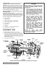
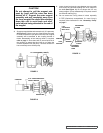
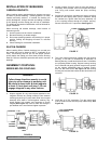
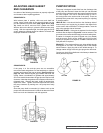
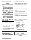
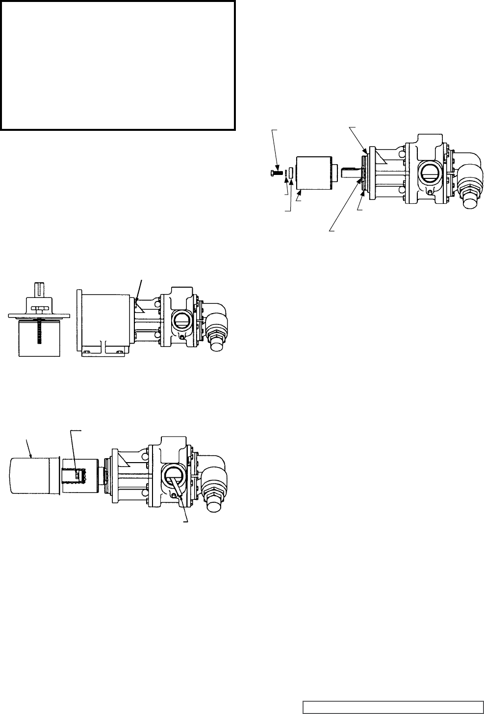
4. Insert a brass bar through a port between two rotor teeth
and loosen the capscrew holding the inner magnet to
the shaft (See Figure 11). Do not forget, this is a very
strong magnet. If pump disassembly is required, remove
the external retaining ring.
5. Do not remove the O-ring unless it is bad, especially
if PTFE (Derivative) encapsulated. If a new O-ring is
required, follow instructions in the “Assembly: Pump”
on page 7.
FIGURE 9
FIGURE 10
FIGURE 11
CAUTION !
Do not attempt to pull the magnet sets
apart by hand until the outer has been
backed off 4”. Support the outer magnet
assembly and pull completely away from
the inner magnet. Be careful when setting
down this unit to avoid tools and other
metal objects being attracted to the end of
the magnet.
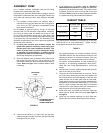
3. Support pump with hoist and remove the (4) .5” capscrews.
See Figure 9. Pull the pump out of the bracket; there will
be some resistance to pull apart since the inner magnet
assembly will be attracted to the coupling bracket. If
further disassembly of the bearing carrier is required,
refer to page 7. Since there will be some liquid left in
the canister, be aware that liquid will run out when the
canister separates from the pump. Remove canister if it
has not already come off the pump.
0.5” CAPSCREWS (4 REQ’D)
0.44”
CAPSCREW
WITH HOLE
SECONDARY
O-RING
0.44” CAPSCREW RIGHT
HAND THREADS
CANISTER
BRASS BAR
WASHER
LOCK
WASHER
INNER
MAGNET
EXTERNAL
RETAINING
RING
PRIMARY
O-RING


