


SECTION TSM 845 ISSUE F PAGE 11 OF 14
ADJUSTING HEAD GASKET
END CLEARANCE
PUMP ROTATION
Use either of the following procedures to properly adjust the
end clearance when replacing gaskets:
PROCEDURE A:
With balance plate in position, slide rotor and shaft into
casing. Insert a feeler gage of the proper thickness into the
port and between two rotor teeth (See Figure 20 on page
10). Install one 0.015” and one 0.007” gasket onto head.
With the idler on the idler pin, place the head into the pump
casing. With the capscrews tight, the feeler gage should fit
snugly, otherwise gaskets should be added or removed until
the proper clearance is attained.
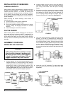
The pump is designed to take fluid from the discharge side
of the pump and channel it down the idler pin into the shaft
and out into the canister through the capscrew which secures
the inner magnet. The fluid is returned through a hole in
the casing back to the suction side of the pump. There are
generally three parts which may need replacing or adjusting
to change rotation.
HEAD & PIN – Hole should be from the discharge side of
head to the pin and a pipe plug is placed in the tapped hole
on the suction side of the head. To change rotation, move the
plug to the opposite side of the head.
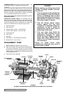
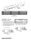
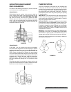
BALANCE PLATE – If the plate is separate from the bracket
and looks like the Style A in Figure 22, it can be reversed. The
groove should connect the discharge port to the bushing bore.
If rotation is changed, the plate is flipped over (not rotated)
and the groove would not be visible but will still function
properly. If the plate is like Style B, it is NOT reversible and a
new plate will be required.
BRACKET – The bracket will have two holes drilled through
and tapped on one side. The discharge side of the bracket
should feature a pipe plug with a hole drilled through it. To
change rotation simply move this pipe plug to the other hole.
Contact your local Viking distributor or the factory to determine
which parts are required.
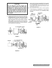
PROCEDURE B:
If the pump is in line and the ports are not accessible,
remove the head and gaskets. Put the head back on (without
gaskets) and measure the gap as shown. (See Figure 21 on
page 10). After determining the gap between the head and
casing, select a combination of gaskets with approximately
25% more total thickness than the gap plus the required end
clearance. Note that the gaskets will compress when head is
tightened down. Remove the head, install all gaskets then
replace the head. Tighten the head capscrews and check
the pump clearance by making sure the pump turns freely
by hand.
Since the pump shaft is concealed, it is best to work up the
proper end clearance because it is difficult to determine when
there is to much end clearance with this approach.
FIGURE 20
FIGURE 21
FIGURE 22
STYLE BSTYLE A
GROOVE