


www.desatech.com 113052-01A
16
O
F
F
P
I
L
O
T
LIGHTING
INSTRUCTIONS
1. STOP! Read the safety information, page
15, column 2.
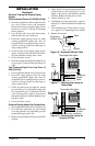
2. Make sure equipment shutoff valve is fully
open.
3. Turn thermostat control knob clockwise
Clockwise
to the OFF position (see Figure 22
or 23 for your model).
4. Wait five minutes to clear out any gas. Then
smell for gas, including near the floor. If
you smell gas, STOP! Follow “B” in the
safety information, page 15, column 2. If
you don’t smell gas, go to the next step.
5. Turn thermostat control knob counter-
clockwise
C-clockwise
to the PILOT position.
Press in thermostat control knob for 5 sec-
onds (see Figure 22 or 23 for your model).
Note:
You may be running this heater for
the first time after hooking up to gas supply.
If so, you may need to press in thermostat
control knob for 30 seconds or more. This
will allow air to bleed from the gas system.
• If thermostat control knob does not pop
up when released, contact a qualified ser-
vice person or gas supplier for repairs.
6. Keep thermostat control knob pressed in while
pushing down and releasing the ignitor but-
ton. This will light pilot. If necessary, continue
to press ignitor button until pilot lights.
If pilot does not light
• turn thermostat control knob clockwise
Clockwise
to the OFF position
• repeat steps 5 and 6
If pilot does not stay lit after several tries
• refer to Troubleshooting, pages 20 through 22
• contact a qualified service person or gas
supplier
Until repairs are made, light pilot with
match. To light pilot with match, see
Manual Lighting Procedure, page 17.
7. Keep thermostat control knob pressed in
for 30 seconds after lighting pilot. After 30
seconds, release control knob.
Note:
If pilot goes out, repeat steps 3
through 7. This heater has a safety inter-
lock system. Wait one minute before light-
ing pilot again.
OPERATING HEATER
Continued
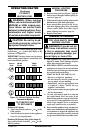
8. Turn thermostat control knob counter-
clockwise
C-clockwise
to the desired heating
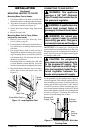
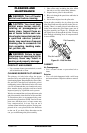
level. For models, VP16TA, VN18TA,
VP26TA, and VN30TA, the main burner
should light. Set control knob to any heat
level between 1 and 5 (see Figure 25). For
infrastat models, the plaque directly above
the pilot should light.
CAUTION: Do not try to ad-
just heating levels by using the
equipment shutoff valve.
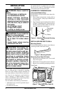
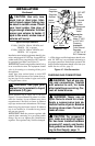
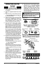
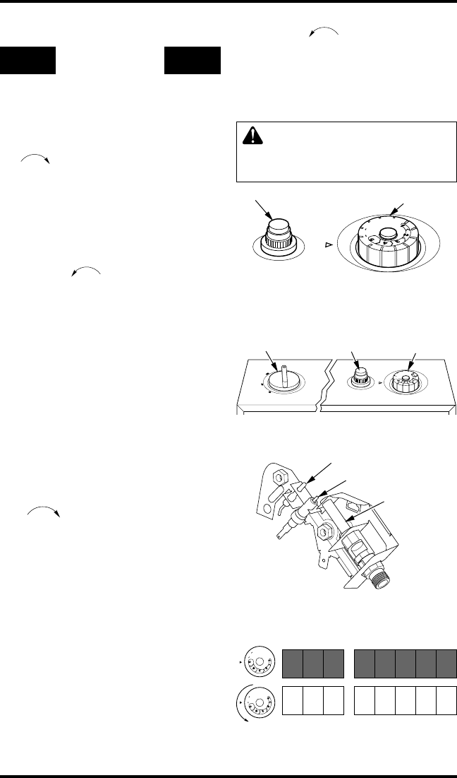
Figure 22 - Control Knob In The OFF
Position, Models VP16TA, VN18TA,
VP26TA, & VN30TA
Control Knob
Ignitor Button
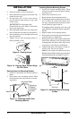
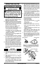
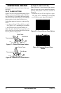
Figure 24 - Pilot
Figure 25 - Burner Patterns
O
F
F
P
I
L
O
T
O
F
F
P
I
L
O
T
Control
Knob
VP16TA
VN18TA
VP26TA
VN30TA
Ignitor Electrode
Pilot Burner
Thermocouple
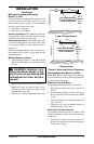
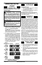
Figure 23 - Thermostat Control Knob In The
OFF Position, Models VP16ITA & VN22ITA
1
2
3
4
O
F
F
P
I
L
O
T
Thermostat
Control Knob
Plaque Control
Knob
Ignitor
Button