


13
104820
OWNER’S MANUAL
INSPECTING
BURNER
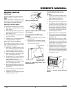
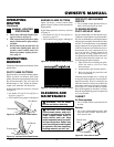
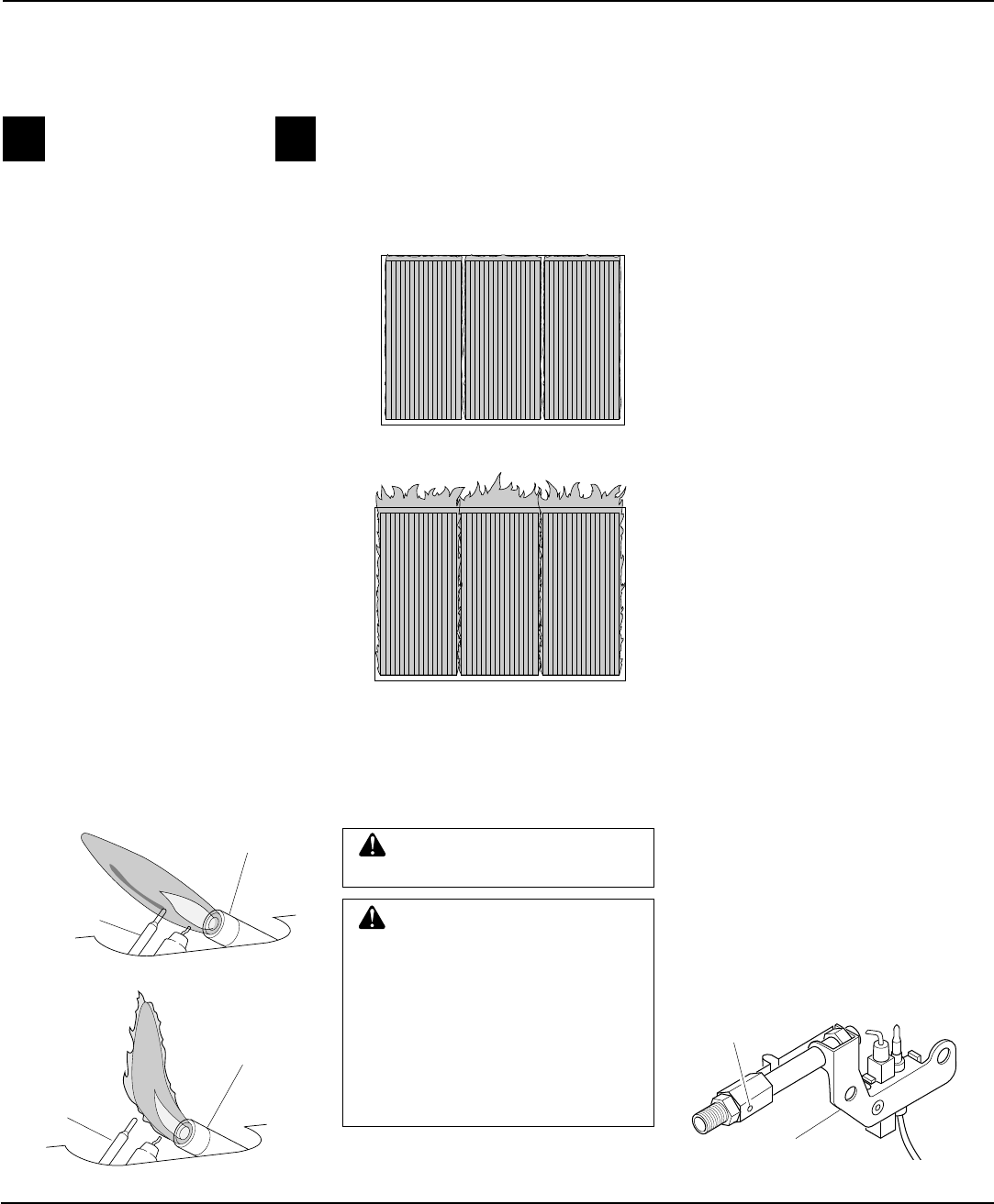
Check pilot flame pattern and burner flame
pattern often.
PILOT FLAME PATTERN
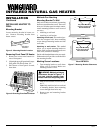
Figure 18 shows a correct pilot flame pattern.
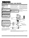
Figure 19 shows an incorrect pilot flame
pattern. The incorrect pilot flame is not touch-
ing the thermocouple. This will cause the
thermocouple to cool. When the thermo-
couple cools, the heater will shut down.
If pilot flame pattern is incorrect, as shown
in Figure 19
• turn heater off (see To Turn Off Gas to
Appliance, page 12)
• see Troubleshooting, pages 14 through 16
GRH/OV 009GOOD PILOT
Figure 18 - Correct Pilot Flame Pattern
Thermocouple
GRH/OV 010BAD PILOT
Thermocouple
Figure 19 - Incorrect Pilot Flame Pattern
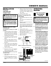
Pilot Burner
Pilot Burner
Figure 20 - Correct Burner Flame Pattern
Bad Burner Pattern-Plaque
GRH/OV 019
Figure 21 - Incorrect Burner Flame Pattern
BURNER FLAME PATTERN
Figure 20 shows a correct burner flame
pattern. Figure 21 shows an incorrect burner
flame pattern.
If pilot flame pattern is incorrect, as shown
in Figure 21
• turn heater off (see To Turn Off Gas to
Appliance, page 12)
• see Troubleshooting, pages 14 through 16
CLEANING AND
MAINTENANCE
ODS/PILOT AND BURNER
ORIFICE
• Use a vacuum cleaner, pressurized air, or
small, soft bristled brush to clean.
CLEANING BURNER
PILOT AIR INLET HOLE
We recommend that you clean the unit every
2,500 hours of operation or every three months.
We also recommend that you keep the burner
tube and pilot assembly clean and free of dust
and dirt. To clean these parts we recommend
using compressed air no greater than 30 PSI.
Your local computer store, hardware store, or
home center may carry compressed air in a
can. You can use a vacuum cleaner in the
blow position. If using compressed air in a
can, please follow the directions on the can. If
you don't follow directions on the can, you
could damage the pilot assembly.
1. Shut off the unit, including the pilot.
Allow the unit to cool for at least
thirty minutes.
2. Inspect burner, pilot for dust and dirt.
3. Blow air through the ports/slots and
holes in the burner.
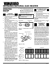
Clean the pilot assembly also. A yellow tip
on the pilot flame indicates dust and dirt in
the pilot assembly. There is a small pilot air
inlet hole about two inches from where the
pilot flame comes out of the pilot assembly
(see Figure 22). With the unit off, lightly
blow air through the air inlet hole. You may
blow through a drinking straw if compressed
air is not available.
CABINET
Air Passageways
• Use a vacuum cleaner or pressurized air
to clean.
Exterior
• Use a soft cloth dampened with a mild
soap and water mixture. Wipe the cabi-
net to remove dust.
CAUTION: You must keep
control areas, burner, and circu-
lating air passageways of heater
clean. Inspect these areas of
heater before each use. Have
heater inspected yearly by a quali-
fied service person. Heater may
need more frequent cleaning due
to excessive lint from carpeting,
bedding material, pet hair, etc.
WARNING: Turn off heater
and let cool before cleaning.
MANUAL LIGHTING
PROCEDURE
1. Follow steps 1 through 5 under Light-
ing Instructions on page 12.
2. With control knob pressed in, strike
match. Hold match to pilot until pi-
lot lights.
3. Keep control knob pressed in for 30
seconds after lighting pilot. After 30
seconds, release control knob. Now
follow step 8 under Lighting Instruc-
tions, page 12
OPERATING
HEATER
Continued
Figure 22 - Pilot Inlet Air Hole
Pilot Assembly
Pilot Air Inlet
Hole