


4
106056-01
GAS RESIDENTIAL HEATERS
®
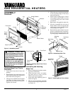
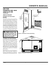
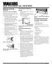
Attaching Brass Front Trim to
Front Panel
1. Locate brass front trim in brass trim
package.
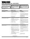
2. Slide the head of two truss-head screws
from hardware packet into each end of
brass front trim (see Figure 5).
3. Line up screws with holes in front panel
(see Figure 4). Insert screws in holes.
Attach nuts from inside of front panel.
Tighten with wrench.
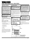
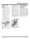
5. Slide other end of adjusting plate/shim
in slot on mitered edge of side brass
trim (see Figure 6).
6. While firmly holding edges of brass
trim together, tighten both set screws
on the adjusting plate with slotted
screwdriver.
7. Repeat steps 1 through 6 for other side.
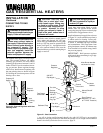
8. Place the assembled trim on front of
heater cabinet. Attach on top and sides
with four brass screws included in hard-
ware package (see Figure 7).
9. Reattach front panel to heater if you are
going to mount the heater to the base.
Do not reattach front panel at this time
if you are going to mount heater to wall.
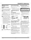
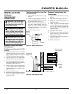
Log
Retaining
Brackets
Figure 4 - Assembling Heater
Truss-Head
Screw
Nut
Front Panel
Figure 5 - Attaching Brass Front Trim to
Front Panel
Brass Front Trim
Top Brass
Trim
Slot
Mitered Edge
Slot
Set
Screws
Adjusting
Plate
Screws
Assembled
Brass Trim
Shim
Figure 6 - Assembling Brass Trim
Figure 7 - Attaching Brass Trim to Heater
WARNING: Always have
burner shield and screen in place
before operating heater. This pre-
vents excessive temperatures on
heater surfaces.
Failure to position the parts in
accordance with these diagrams
or failure to use only parts spe-
cifically approved with this heater
may result in property damage or
personal injury.
Side Brass
Trim
ASSEMBLY
Continued
Burner Shield
Screen
Front Panel
Deflector
Log
Truss-
Head
Screw
Brass Front Trim
Screw
Screw
Heater Cabinet
Nut
Assembling and Attaching
Brass Trim
1. Remove packaging from three remain-
ing pieces of brass trim.
2. Locate four brass screws, two adjust-
ing plates with set screws, and two
shims in the hardware packet.
3. Align shim under adjusting plate as
shown in Figure 6.
4. Slide one end of adjusting plate/shim
in slot on mitered edge of top brass trim
(see Figure 6).