


12
107101
NATURAL GAS RESIDENTIAL HEATERS
®
For more information, visit www.desatech.com
INSTALLATION
Continued
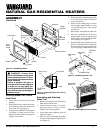
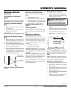
C. MOUNTING HEATER
TO
OPTIONAL MANTEL
See Instructions Included
With Mantel Kit
Assembling Mantel
IMPORTANT:
Only use the optional man-
tels specified in this manual. See Accesso-
ries, page 23 for proper mantel kits. This
heater is only approved for use with models
GMF800/GMU801 series, GM900F/
GM901U series, GM902F/GM903U series,
GM700F/GM701U series, and GM702F/
GM703U series mantel kits. Using any other
mantel will void the CSA approval for this
heater. Only use models GMF800/GMU801
series, GM900F/GM901U series, GM902F/
GM903U series, GM700F/GM701U series,
and GM702F/GM703U series mantels with
this heater. Do not use these mantels with
any other product.
* An CSA design-certified equipment shutoff valve with 1/8" NPT tap is an acceptable
alternative to test gauge connection. Purchase the optional CSA design-certified equipment
shutoff valve from your dealer. See Accessories, page 23.
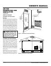
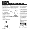
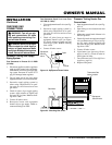
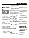
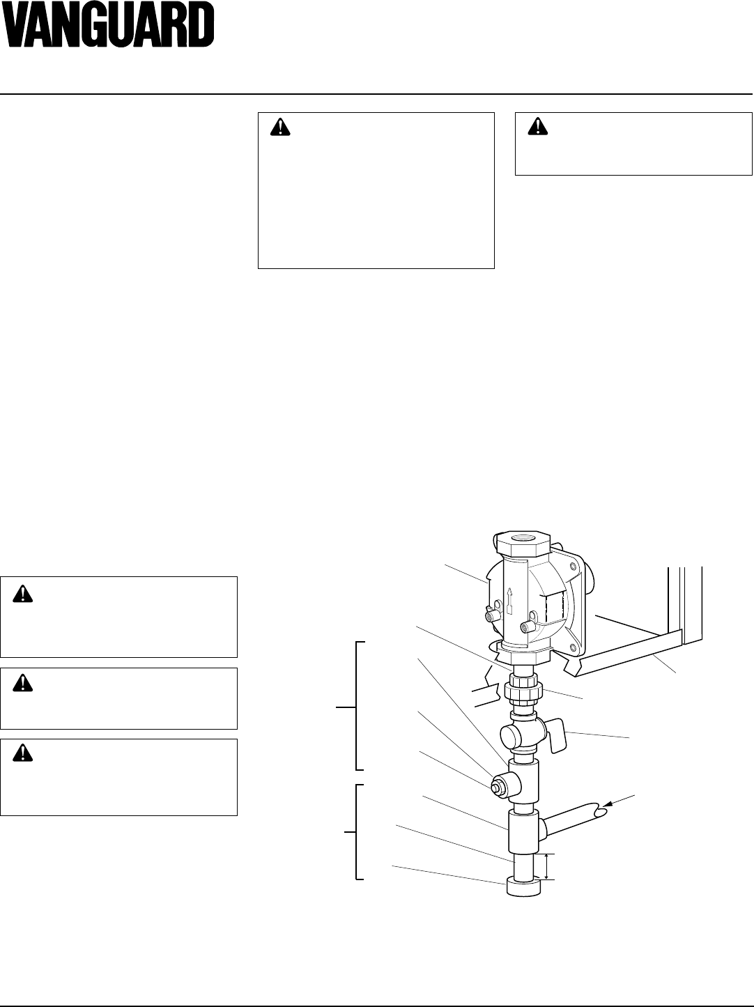
Figure 18 - Gas Connection
CONNECTING TO GAS
SUPPLY
WARNING: A qualified service
person must connect heater to gas
supply. Follow all local codes.
WARNING: Never connect
heater to private (non-utility) gas
wells. This gas is commonly
known as wellhead gas.
IMPORTANT:
Check gas line pressure be-
fore connecting heater to gas line. Gas line
pressure must be no greater than 14 inches
of water. If gas line pressure is higher,
heater regulator damage could occur.
CAUTION: Use only new,
black iron or steel pipe. Inter-
nally-tinned copper tubing may
be used in certain areas. Check
your local codes. Use pipe of 1/2"
or greater diameter to allow
proper gas volume to heater. If
pipe is too small, undue loss of
pressure will occur.
Installation must include an equipment
shutoff valve, union, and plugged 1/8" NPT
tap. Locate NPT tap within reach for test
gauge hook up. NPT tap must be upstream
from heater (see Figure 18).
IMPORTANT:
Install an equipment shutoff
valve in an accessible location. The equip-
ment shutoff valve is for turning on or
shutting off the gas to the appliance.
Apply pipe joint sealant lightly to male
threads. This will prevent excess sealant
from going into pipe. Excess sealant in pipe
could result in clogged heater valves.
CAUTION: Use pipe joint seal-
ant that is resistant to liquid pe-
troleum (LP) gas.
We recommend that you install a sediment
trap in supply line as shown in Figure 18.
Locate sediment trap where it is within
reach for cleaning. Install in piping system
between fuel supply and heater. Locate sedi-
ment trap where trapped matter is not likely
to freeze. A sediment trap traps moisture
and contaminants. This keeps them from
going into heater controls. If sediment trap
is not installed or is installed wrong, heater
may not run properly.
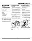
IMPORTANT:
Hold pressure regulator with
wrench when connecting it to gas piping
and/or fittings.
Tee Joint
Reducer
Bushing to
1/8" NPT
1/8" NPT
Plug Tap
Test Gauge
Connection *
Tee Joint
Pipe
Nipple
Cap
Sediment
Trap
Pressure
Regulator
3/8" NPT
Pipe Nipple
Ground
Union
Joint
Heater Cabinet
3" Minimum
Note:
Burner bracket
not shown for clarity
Equipment Shutoff
Valve *
From Gas Meter
(5" W.C. to 10.5"
W.C. Pressure)
WARNING: This appliance re-
quires a 3/8" NPT (National Pipe
Thread) inlet connection to the
pressure regulator.