


14
102885
INSTALLING
Continued
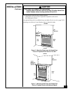
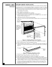
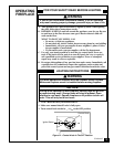
Figure 12 - Attaching Brass Trim to Fireplace
Shoulder
Screws
Assembled
Brass Trim
OPTIONAL MANTEL INSTALLATION
Note:
Refer to instructions provided with the mantel for assembly instructions. Refer to
instructions below for system installation. Refer to instructions on page 5 for firebox
assembly. Blower accessory should be installed if it is being used (see Accessories, page 29).
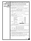
1. Unscrew four brass screws that attach top louver to fireplace. Remove louvre
from fireplace and set aside.
2. Place fireplace on wood base.
3. Place mantel around fireplace/base assembly.
4. Assemble brass trim kit. See Assembling Brass Trim, page 15.
5. Firmly snap brass trim kit on shoulder screws. Shoulder screws are located on
fireplace cabinet (see Figure 12).
6. Align brass trim kit for flush fit around opening.
7. Use two 3" wood screws provided and attach fireplace base to wooden base (see
Figure 12).
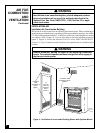
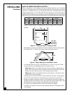
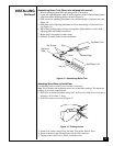
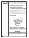
Figure 13 - Attaching Wood Base to Floor
1
3
/4" Screw
Wood
Base
Hole for 3"
wood screw
for attaching
fireplace to
wooden base
Hole for 3"
wood screw
for attaching
fireplace to
mantel
8. Remove brass trim kit and mantel. Be careful not to damage wall or mantel.
9. Place wood base next to wall at installation location.
10. Attach wood base to floor with two 1
3
/4" black screws provided (see Figure 13).
If the floor is concrete use anchor method (see Attaching Wood Base to Solid Floor,
page 15).
11. Install gas line. See Connecting To Gas Supply, pages 16.
12. Check for leaks. See Checking Gas Connections, page 17.
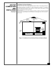
13. Place mantel around fireplace. Be careful not to damage wall or mantel.
14. Place brass trim kit on the shoulder screws located on the side and top of the fireplace.
Firmly snap the brass trim over the shoulder screws on fireplace (see Figure 12).
15. Adjust assembly to remove any gaps. Attach remaining two 3" wood screws from
hardware pack through openings inside of fireplace sides into the mantel. The
openings are located at top behind the area for the brass louvers (see Figure 13).
16. Reinstall top brass louvers.