


www.desatech.com
115121-01B 11
ACCESSORy
INSTALLATION
Continued
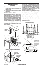
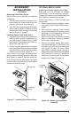
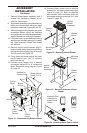
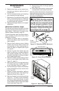
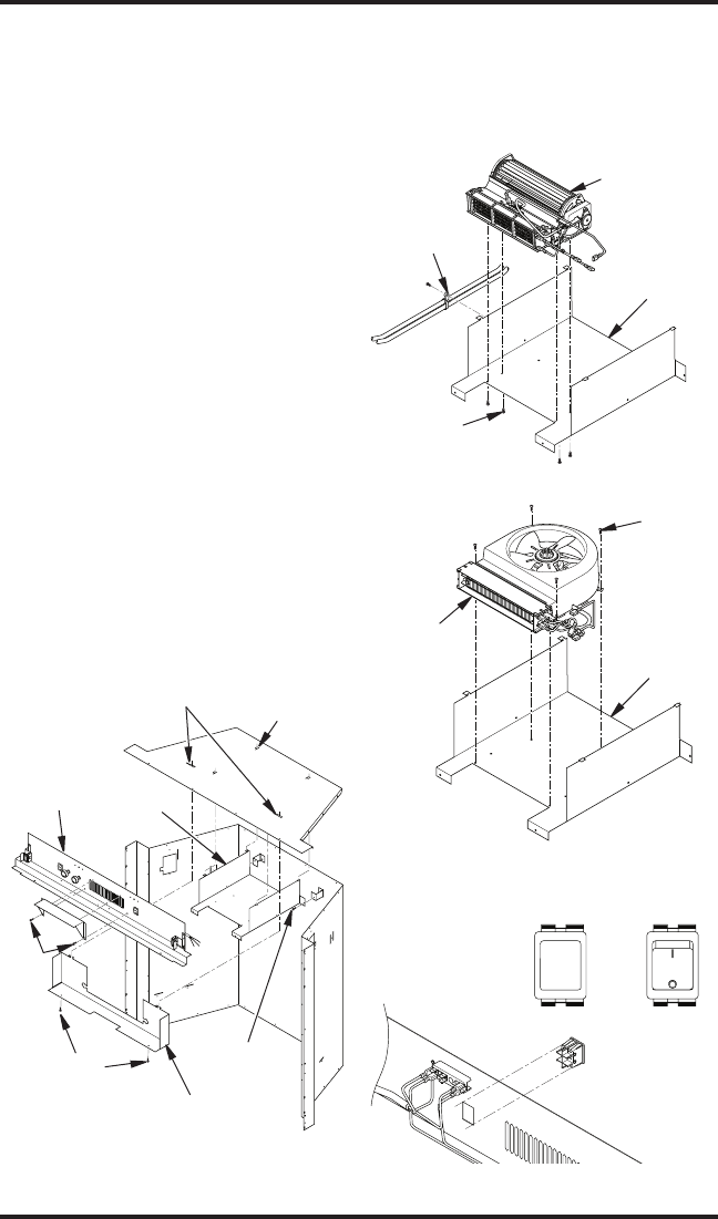
7. Remove blower/heater assembly with 4
screws from packaging. Blower is pre-
wired for convenience.
8. Align blower assembly over hole pattern on
blower mount and attach with 4 pan head
screws provided (see Figures 22 and 23).
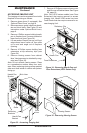
9. With discharge pointing towards you, guide
assembled blower mount into replace
and center rear mounting anges between
standoff brackets at rear of the replace.
10. Lift blower mount up and position 4 locking
tabs through notched openings in rebox
top. Slide assembly forward until locked
into position.
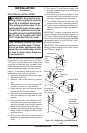
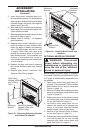
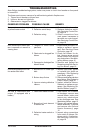
11. Remove control panel knockout plug lo-
cated in heater switch position by pressing
locking tabs and pushing plug out through
front of panel (see Figure 24).
12. Firmly insert red power switch into open
mount location with “ON” (I) indicator
positioned on top.
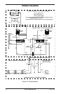
13. Connect white heater wire to neutral
connection marked 'B' or 'A' on terminal
block. See partial wiring diagram, Figure
25, page 12.
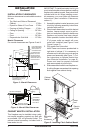
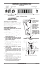
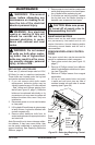
Figure 21 - Disassembling Blower Mount
Control
Panel
Control
Cover
Blower
Mount
Control
Cover
Screws
Hex
Screws
Notches for
Control Cover
Blower Mount
Notch (1 of 4)
Screws
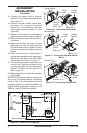
Figure 22 - Mounting Heater/Blower
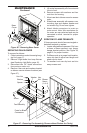
Figure 23 - Mounting Alternate Heater/
Blower
Harness
Strap
Heater/
Blower
Assembly
Blower
Mount
Mounting
Screws
Mounting
Screws
Heater/
Blower
Assembly
Blower
Mount
Figure 24 - Installing Heater Power Switch
Knockout Plug
- Remove to
Install Power
Switch
Power
Switch
14. Connect black heater wire to terminal
marked 'N-1' on heater power switch (see
Figure 26, page 12). Note: On alternate
style heaters white and black wires are
connected common to terminal 'N-1' (see
Figure 27, page 12).