


www.hotwater.com
For Technical Information and Automated Fax Service, call 800-527-1953. A.O. Smith Corporation reserves the right to make product changes or improvements without prior notice.
Recovery capacities based on actual performance tests.
* Dual-channel system has 3˝ vent pipe inside 6˝ air intake pipe, for the 40 & 50 gallon models.
The 75-gallon model uses a 4”x 7” co-axial pipe.
All models have 2” foam cavity.
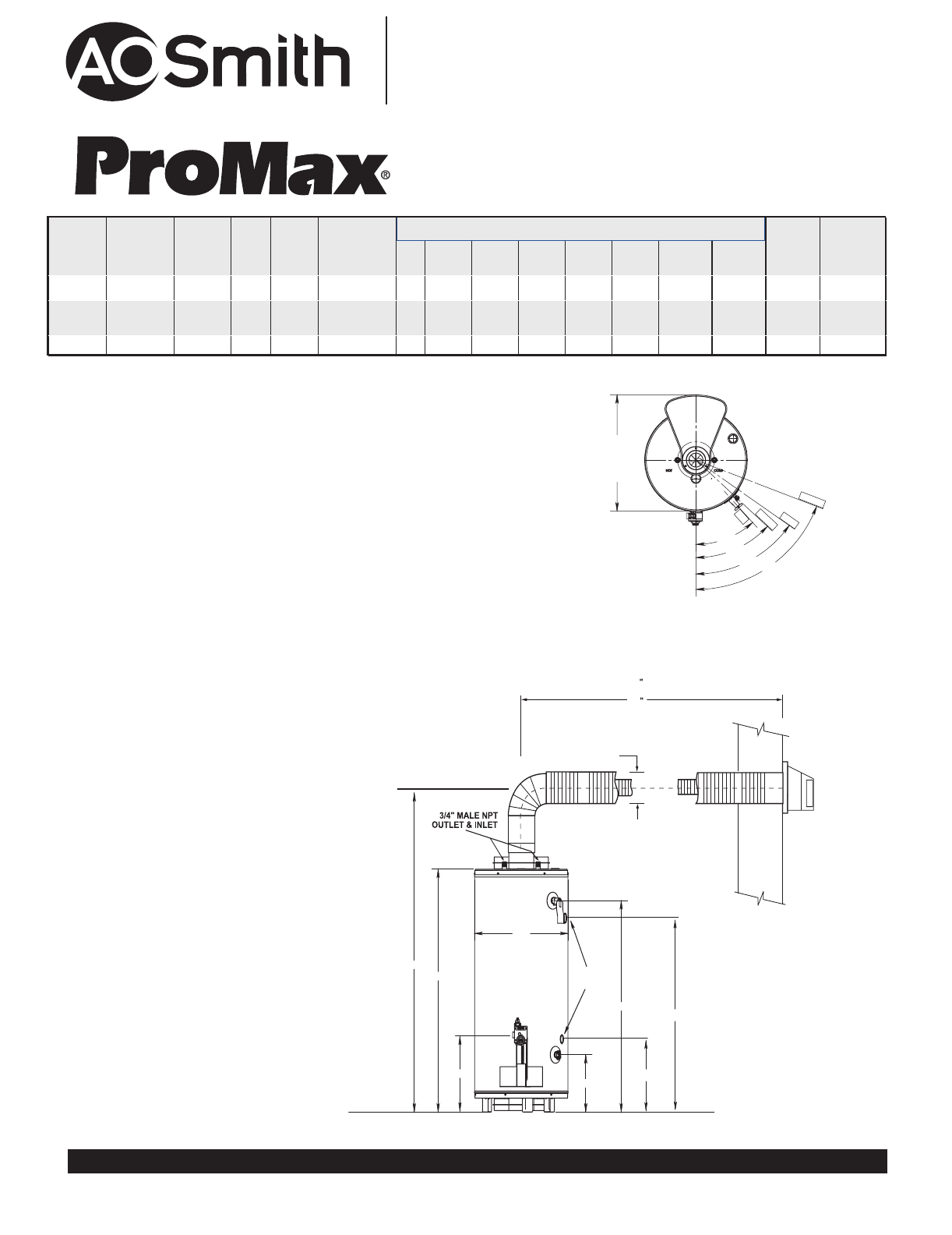
Water connection 3/4” male all models.
All models are certified for sale in Canada (add SMR “T25”).
75 gallon water connections are 12” on center.
E
F
B
A
D
FRONT
MAX VENT
80
C
EXTERIOR
WALL
6 DIA.
MIN VENT
17
SIDE
TAPS
H
G
42°
47°
25-1/4
69°
55°
TOP
INLET
DRAIN
T&P
OUTLET
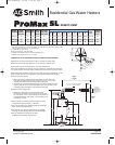
Important! Vent Installation and Termination Requirements
n Maximum horizontal vent distance is 80” to outside of exterior wall.
n Minimum horizontal vent distance is 17” to outside of exterior wall.
n Vent pipes may be trimmed (cut) for short vent installations.
n For vent installation less than 30” the vent restrictor is required. Place restrictor
over the flue outlet on heater before installing the outlet vent pipe to the heater.
n Recommended installation height for the heater vent pipe should be 68” for 40
gallon models and 76” for the 50-gallon and 75-gallon models (vent height).
n Offset Vent Arrangement
1. When replacing an existing direct vent model, the new vent pipe
may drop from the minimum vent height as much as 7 1/4” to exit
through the existing vent opening in the exterior wall.
2. Vent may have one horizontal 90 degree turn before exiting through
exterior wall (Do not combine both offset vent arrangements in one
installation) (See examples in the installation manual)
n High Rise Vent Arrangement
3. When vent termination is more than 80” above
the base of the heater. The horizontal vent run must
be a minimum of 22” from the center of the heater to
the outside exterior wall surface. (See example in the
installation manual)
n Vent termination clearance hole through the exterior
wall should be approximately 7” diameter.
n Snow accumulation and drifting should be considered
when locating the termination.
n An optional wire grill vent cap protector is available
through the parts department, part number 9006627.
n See the installation manual for complete
installation and venting requirements.
Residential Gas Water Heaters
AOSRG46400
Revised April 2008
Page 2 of 2
SL
DIRECT-VENT
40 & 50 gal.
25-1/4
75 gal.
29-1/2
MODEL
NUMBER
FIRST
HOUR
RATING
GALLONS
ENERGY
FACTOR
GAL.
CAP.
BTU
INPUT
PER
HOUR
RECOVERY
90ºF RISE
GALLONS
PER HOUR
A B C D E F
VENT
OUT-
LET*
APPROX.
SHIPPING
WEIGHT
(LBS)
GDV-40L 73 .62 40 38,000 41 68 54-3/4 22-1/4 16 12-1/4 45-1/4 Co-Axial 167
GDVT-50L 88 .59 50 50,000 55 76 64-3/4 22-1/4 16-1/4 12-1/2 55-1/2 Co-Axial 187
GDV-75L 131 .59 75 55,000 60 76 65-3/4 26-1/4 16-1/4 12-1/2 55-1/2 17-1/4 54 Co-Axial 310
DIMENSIONS IN INCHES
41-3/4
53-3/4
16-1/2
16-1/2
G
H
6” DIA. on 40 & 50 Gallon Models
7” DIA. on 75 Gallon Models
75 gal vent
termination
cap is not
interchangeable
with vent cap
on 40 & 50 gal
models
194478_AOSRG46400 4/14/08 11:08 AM Page 2