


2. Wiring Instructions:
a. The appropriate power supply is 120 Volt single phase power supplied from a non-
switchable circuit NOT protected by a ground fault circuit interrupter.
b. Turn off main power to the circuit before wiring the smoke alarm.
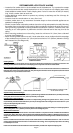
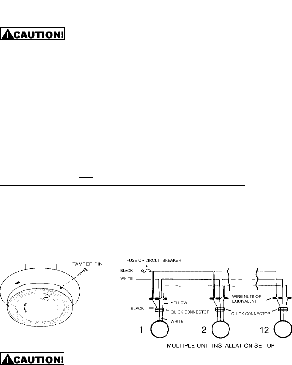
c. There are three pigtail leads (black, white and yellow) coming from the AC QUICK
CONNECTOR. The proper wire connection is as follows:
WIRES FROM QUICK CONNECTOR CONNECT TO
BLACK "HOT" side of AC line
WHITE "NEUTRAL" side of AC line
YELLOW Interconnect wires of other units
For units that are used as single smoke alarms, do not connect the yellow wire to anything.
Insulate this wire (tape it) in place to make certain the yellow wire cannot contact any metal parts.
Interconnected units can provide earlier warning of fire than stand-alone units, especially
if a fire starts in a remote area of the dwelling. This smoke alarm may be interconnected
with as many as 11 other UNIVERSAL model smoke alarms such as SS-785, SS-790,
SS-795, SS-2795, SS-2895 and 6 other units which may be a combination of Carbon
Monoxide Alarms such as CD-9385, CD-9390, CD-9485, CD-9490, CD-9795, Heat Alarms/
HD-130 or Relay Modules/RM-100 for a total of not more than 18 interconnected devices.
Interconnected CO alarms will only respond if a CO alarm / event initiates the alarm. All
other alarms remain silent.
Interconnected smoke alarms, heat alarms and relay modules will only respond if a smoke
alarm / event or heat alarm / event initiates the alarm. All CO alarms remain silent.
Note that units without battery backup will not respond during an AC power failure.
NOTE: Relay Modules/RM-100 will not respond if a CO alarm / event initiates the alarm.
The yellow wire is used
only for multiple station operation with UNIVERSAL models only.
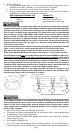
Connecting this yellow wire to any other circuits may result in damage. When smoke
alarms are interconnected, all units must be powered from a single AC branch circuit. If
local codes do not permit be sure the neutral wire is common to both phases. The maximum
wire run distance between the first and last smoke alarm in an interconnected system is
1,000 feet. NOTE: Use standard household wire (18 gauge or larger, rated at least 300V, as
required by local codes) available at all electrical supply/hardware stores.
The wiring to be used shall be in accordance with the provisions of Articles 210 and
300.3(B) of the National Electrical Code, ANSI/NFPA 70. In addition, the resistance of the
interconnecting wiring shall be a maximum of 10 Ohms.
Early warning fire detection is best achieved by the installation of fire detection equipment
in all rooms and areas of the household as follows: A smoke alarm installed in each
separate sleeping area (in the vicinity of, but outside of, the bedrooms) and heat or smoke
alarms in living rooms, dining rooms, kitchens, hallways, attics, furnace rooms, closets,
utility storage rooms, basements and attached garages. Test the smoke alarm weekly to
assure proper operation.
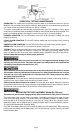
3. Attach the mounting ring to the electrical junction box.
4. To activate 9 volt battery and smoke alarm, pull and remove the thin colored plastic tab at
the battery door hinge. Discard plastic tab.
5. Plug the AC QUICK CONNECTORS together. Push and turn the smoke alarm clockwise
onto the mounting ring.
6. See "TAMPER LOCKING PIN."
7. Turn on AC power and check the LED's for proper operation. The green LED lights to
indicate AC power. The red LED will flash every 40-60 seconds to indicate proper operation.
Page 4