


13
Installation
Please see all methods of Installation
in Appendix at the rear of this booklet.
This is a furnace, not a free standing stove.
You must direct heated air from 8" outlets away
from the furnace, or it will not function properly.
1. This installation must be done by a qualified
heating equipment installer.
2. The installation is to be done in compliance
with National Fire Protection Association installa-
tion standards: No. 89M, 90B, 211, 70 (National
Electric Code) and Uniform Mechanical Code
913, 6-4, in the states where applicable. (Their
code offers connecting smoke pipe connectors
into chimney with other fuel burning appliances.)
3. Rooms large in comparison with size of the
appliances:
a) Wood or Coal Burning Furnace needs air for
combustion and circulation to house.
b) Provision must be made to make up this air
and not starve gas or oil furnace of combustion
air.
c) Have "Authority Having Jurisdiction" deter-
mine that air is of adequate makeup. (Reference
N.F.P.A. Nos. 30 & 54, Code for Installation of
Gas & Oil Equipment)
4. Have "Authority Having Jurisdiction" to
inspect all chimneys and installations for ad-
equate venting and for compliance with standard
and local codes and regulations regarding instal-
lation of wood burning appliances.
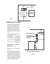
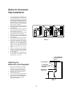
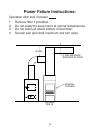
5. Installation of Supplemental Heat Applica-
tion to Existing Central System. (See Fig. 2 for
typical installation.)
a) Place Wood or Coal Burning Furnace so that
the chimney connector will be as short as pos-
sible and avoiding unnecessary sharp turns in the
smoke pipe connector and the installation of
devices that would create excessive resistance
to the flow of flue gases.
b) Locate the Wood or Coal Burning Furnace as
close as practical to the existing central hot air
heating system, maintaining clearances as stated
on the label below the fuel door.
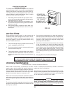
c) Clearances from combustible materials must
be complied with as stated on the label below the
fuel door:
Unit to Combustible:
Front: 48"
Back: 30"
Sides: 12"
Plenum to Ceiling: 6"
Pipe to Combustible:
Sides: 21"
Back: 18"
The installation must be made only on a
noncombustible floor.
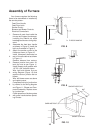
d) Install the smoke pipe connector to the
chimney with 26-gauge pipe and elbows (to be
purchased separately), maintaining the proper
clearances for the specific model. Make sure that
the proper clearances as stated on the label and
earlier in this manual are maintained. Seal the
smoke pipe in the chimney with furnace cement.
(The chimney connector shall be securely sup-
ported, and joints fastened with sheet metal
screws or rivets.)
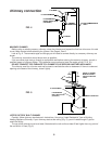
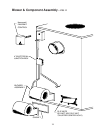
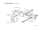
e) Install 8" diameter heat pipe to plenum of the
central hot air furnace. Use 26-guage pipe and
connectors (to be purchased separately). (See
Fig. 14) If central air conditioning is installed in the
plenum, install heat pipe above the air condition-
ing unit. Secure heat pipe connection with sup-
ports and sheet metal screws.
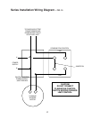
f) Connect electrical supply in the electrical
junction box that is mounted on the back of the
Wood Burning Furnace. See Wiring Diagram (Fig.
12). Remove the cover from electrical junction
box connect power supply wires to wires desig-
nated, using wire nuts. The power cord supplied
may be used for installation, if permitted by local
codes and regulations. If the power cord supplied
cannot be used, the power supply wiring must be
90 degrees Centigrade in a metal cable and
should be completed by a qualified installer com-
plying with NFPA Standard No. 70 and local
codes.
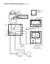
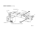
g) Optional Plenum Fan Control Switch (Part
No. 11PCS) is available for installation on the
plenum of central hot air heating furnace. The
purpose of this switch is to activate the circulating
fan of the central hot air heating furnace when the
temperature in the plenum exceeds 120 degrees
Fahrenheit. The switch would activate the fan at
120 degrees Fahrenheit, and would shut off the
circulating fan when the temperature in the ple-
num is reduced to 100 degrees Fahrenheit . This
avoids overheating the plenum.
The electrical supply for operation of this fan
control switch is to be obtained from same elec-
trical supply as the central hot air heating system.
(See Fig. 14) Follow the instructions of the wiring
diagram (Fig. 15). Do not make connections
across Limit Control in the furnace.
Make electrical connections in electrical junc-
tion box presently mounted on the furnace. Make
electrical connections in accordance with NFPA
Standard No. 70 and local codes in the power
supply junction box (See Fig. 15). The wiring to
complete the connections should be 18 AWG
minimum copper and 90 degrees Centigrade in a
cable.