


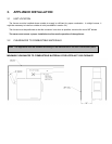
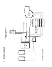
3.5 ELECTRICAL CONNECTION
The following instructions do not supersede the local code.
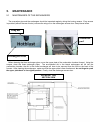
HOTBLAST 1950
On the Hotblast 1950 the combined limit control is installed with the support provided on the left side of the
appliance (two holes are predrilled on the edge of the furnace), and connected to the electrical box along with the
transformer. Install the damper motor on the right side of the front facade above the door (use pre-drilled holes).
The chain that links the air inlet latch to the motor must have a play of 1/8 in. When there is no call for heat, the air
inlet latch must be completely shut and the chain must be affixed to the damper motor at the “8 o’clock” position.
*
WARNING: USE WIRES SUITABLE FOR 75
O
C (167
O
F) ONLY.
* (With all reserves on the minimum combustion air to be increased depending on the type and quality of the
combustible).
3.6 THERMOSTAT
The thermostat must be installed on an inside wall in a location where it is not likely to be affected by the draft
coming from an air outlet. It must be installed at a minimum of 55 inches above the floor.
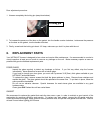
3.7 FAN CONTROL
The fan control setting may vary depending on the type of installation; the “fan OFF” temperature is preset at
110
o
F and the “fan ON” at 150° F at the factory. This setting should provide a proper operation for most
installations.
For a prolonged operation of the blower, it is preferable that the “fan OFF” setting be low enough. But a “fan OFF”
setting too low will cause undesirable cold air circulation. To modify the setting, move the tab on the temperature
dial of the fan limit control at the desired position.
The adjustment of all controls must be performed by a qualified technician. The controls setting and the blower
speed must conform to the recommendations of the “Warm Air Heating and Air Conditioning National Association”.
To obtain a continuous air circulation during summer, move the manual switch ON.
8