


USSC Page 15
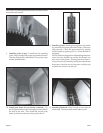
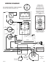
6. Attach low voltage thermostat No. 18 up to 30 ft. run
No. 16 to 15ft. Run (purchase locally) to terminal plate,
screws identified with letters G & R. (Generally top
row center, bottom row right). Snake wire through
holes in top of box. Replace outer covers & control
knob. Under no circumstances should you attempt to
plug in main power cord until all wiring and covers are
in place. NOTE: A ground power cord plug is pro-
vided; however, local codes may require fuse box
mounting.
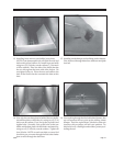
8. Install top shroud (if removed) by simply placing shroud
on to the top of unit, push down, check each corner for
snug fit.
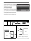
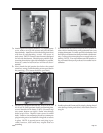
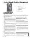
Attaching furnace control center box. To separate outer
cover, remove two (2) side screws and pull off black
rheostat knob. Attach box to left side (facing feed door)
with four (4) self-threading screws. One screw in
each corner. (NOTE: Furnace control center is designed
for left side attachment. Should space prohibit such,
reversing shrouds for right side installation is possible,
however, control wires from box will have to be ex-
tended.)
Next, attach the 4x4 junction box below the control
center box, using (2) self-threading screws provided in
the parts bag. (Two starter holes are provided.)
5a.
5b.
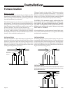
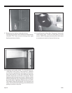
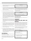
Wall thermostat should be mounted on an upstairs in-
side wall (no outside facing wall) preferably near your
existing thermostat. For more specific information, read
the Honeywell instruction sheet provided with thermo-
stat. Caution: disconnect the power supply before in-
stalling. NOTE: Your wall thermostat and transfer re-
lay are mated Honeywell products for trouble free in-
stallation.
7.