


11
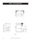
•DRAWINGS FOR ILLUSTRATION PURPOSES ONLY•
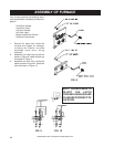
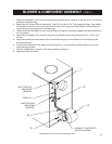
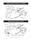
BLOWER & COMPONENT ASSEMBLY - FIG. 11
JUNCTION BOX
MOUNTING
BRACKET
1. Attach the Honeywell Limit Control to the bracket as shown below, using (2) of the #12 x 3/4" Tek Screws
provided in the parts bag.
2. Attach the 2x4 Junction Box to the bracket. Use (2) of the #12 x 3/4" Tek Screws provided. Also, attach
the flexible conduit from the Limit Control to the junction box using one of the Romax Conduit fitting and
red anti-short bushing provided in the parts bag.
3. Unbox the blower and attach to the unit by sliding the flange on the blower between the cabinet back and
the unit bottom.
4. Now attach the blower to the unit by lining up the two holes and mounting blower with (2) 1/4-20 x 3/4"
screws.
5. Attach the conduit from the blower to the junction box using one of the Romax Conduit fitting and red
anti-short bushing.
6. Run the wires from the house supply into the junction box. Use the Romax Cable Clamp and red anti-
short bushing provided.
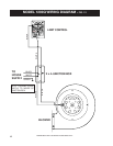
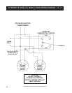
7. Wire the components as shown in the wiring diagram on page 12.
8. Replace junction box cover.
4
5
LIMIT CONTROL
MOUNTING
BRACKET
3
2
1
CONDUIT
CONDUIT TWISTS INTO
MOTOR HOUSING