


2319 Laurelbrook Street, Raleigh, NC 27604 · (800) 542-7221 · FAX (919) 834-4526 · www.ultimate-products.com
-
6
-
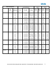
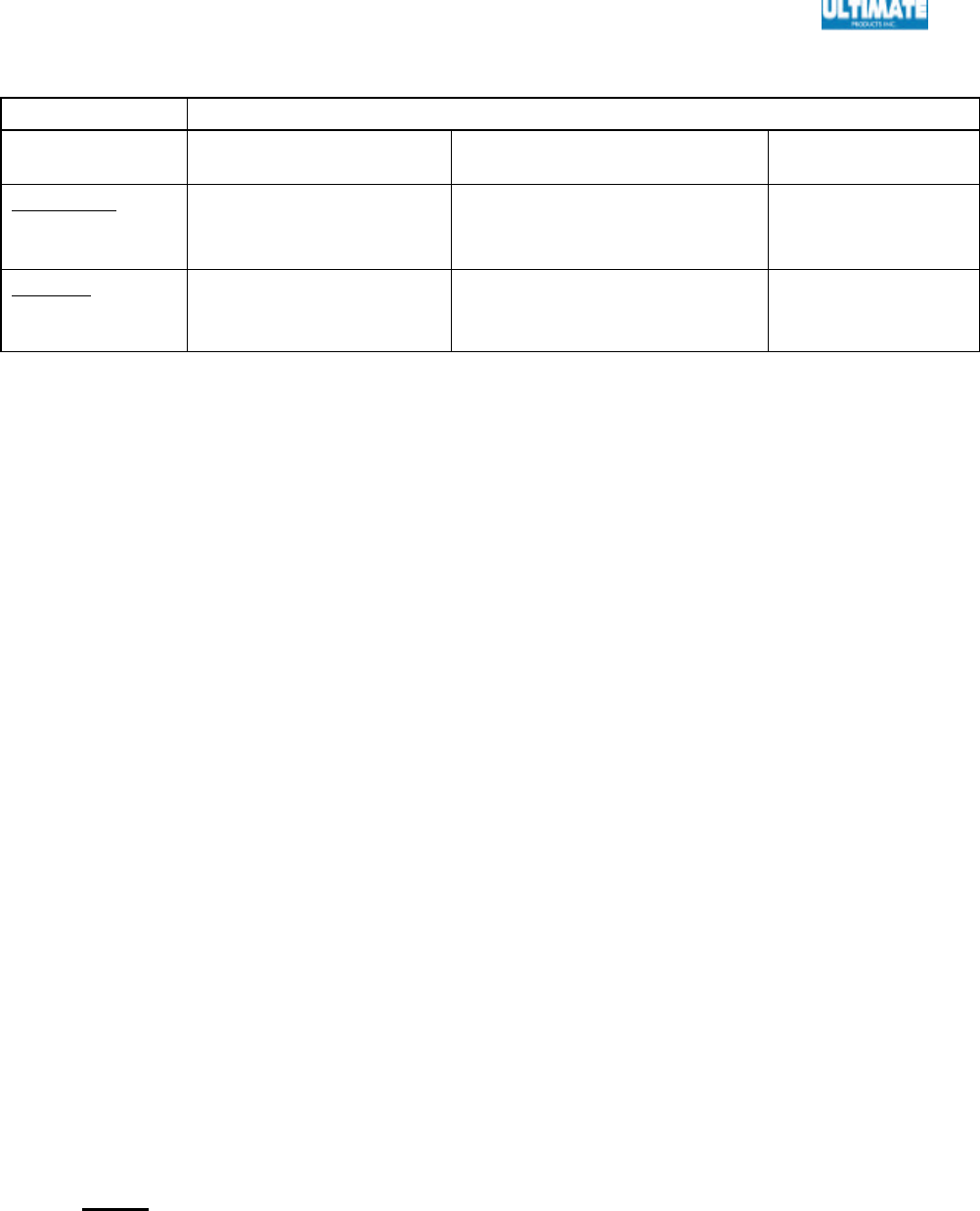
A.3 MOUNTING CLEARANCES (CONT.)
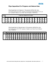
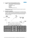
MOUNTING HEIGHT ABOVE FLOOR
Mounting
Position
40,000 – 75,000 B.T.U
100,000 – 130,000 B. T. U. 150,000 B. T. U
Horizontal
Recommended
Minimum
14 ft
12ft
16ft
14ft
18ft
16ft
Inclined
Recommended
Minimum
11ft
10ft
13ft
12ft
15ft
14ft
Ensure that there is adequate provision in the building for combustion and
ventilating air supply. Installation must meet minimum requirements of applicable
codes.
When installed in public garages and airplane hangars ensure that minimum
clearances specified in ANSI/NFPA 88A or B, ANSI/NFPA 409, respectively, are
met; and in no case less than those in the preceding tables.
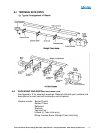
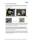
A.4 PRE-ASSEMBLY
Each heating unit is assembled as follows:
Note that the emitter tube consists of more than one tube. The tube to be
connected to the burner box is the thinner stainless steel or aluminized steel
tube. Other tubes may be mild (thicker tubes), stainless or aluminized steel.
Connections between tubes is by a coupling with three bolts. The coupling has
an inner compression sleeve that holds the pipe securely when the nuts are
turned tight.
Support the assembled radiant tube with screws facing upwards, on blocks, etc.
at least 6” above floor level, preferably under the position of installation. Ensure
that the tube is clear internally.
Slip the suspension brackets onto the tube assembly and attach by means of “U”
bolts and nuts. Note that there are two types of brackets; type C and type B.
Type C attaches reflectors together. Bracket C & B are placed on the assembled
radiant tube in position shown on the assembly drawing in APPENDIX “A”.
Tighten nuts to secure brackets to the tubes at spacing indicated with all brackets
oriented in the same level position.
NOTE: CLOSE ALL S-HOOKS TO INSURE THAT THE CHAINS DO NOT
COME OFF OF THE HOOK.