


2319 Laurelbrook Street, Raleigh, NC 27604 · (800) 542-7221 · FAX (919) 834-4526 · www.ultimate-products.com
-
7
-
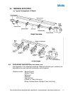
A.5 INSTALLATION
Heater units: At this point raise the tube assembly into position and suspend from
previously fixed chains (9 gauge min. galvanized welded link construction), or
attach to wall mounting brackets. Wall mounting brackets must support heater at
an angle of inclination of 45° ±10°. Longer tube assembly may be raised in more
than one sub-assembly with final tube connection made in the air.
It is recommended that the heater be suspended to slope slightly downward from
the burner approximately 1 inch in 20 feet, but not more than 2-inches total.
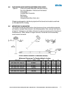
Remove the protective plastic film from the reflector surface. Note that each
section of reflector has two holes punched at one end. This end is firmly fixed by
bolting to the lugs provided on the reflector bracket type C. The other end of each
reflector section is free floating in suspension bracket type B thereby allowing for
thermal expansion.
Position reflector sections so that ends with holes lap at type C brackets and
secure with nuts, bolts, and large washers provided in the burner box crate.
Reflector should be allowed free movement through brackets type B. Note:
Reflectors may be installed before tube is raised to position at installer’s option.
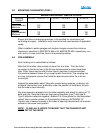
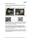
Slide burner/control assembly onto the burner end of the radiant tube ensuring it
is fully engaged and upright, (i.e. with air inlet cover plate facing upwards) and
secure with locking screws provided.
Slide the fan assembly on the opposite end of radiant tube, ensuring that it is fully
engaged with fan outlet facing horizontally for outdoor installations and for indoor
installations either unvented or with horizontal thru wall venting. Fan outlet should
face upward for vertical venting thru the roof.