


2319 Laurelbrook Street, Raleigh, NC 27604 · (800) 542-7221 · FAX (919) 834-4526 · www.ultimate-products.com
-
18
-
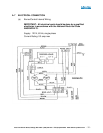
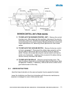
B. 3 REPLACEMENT OF COMPONENTS
WARNING: TURN OFF GAS AND ELECTRICAL SUPPLIES
BEFORE STARTING REPAIR WORK.
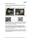
A. TO REPLACE ANY COMPONENTS IN THE BURNER/CONTROL
ASSEMBLY – This assembly should be removed from the heater by
disconnecting the gas and electrical supplies (also the fresh air intake
duct if used). Loosen the bolts and slide the burner/control assembly
from the emitter tube.
B. TO REPLACE ELECTRODE ASSEMBLY – Remove top cover of
combustion chamber by removing six (6) screws. Remove the screws
securing the electrode assembly and pull off the electrode cable
connector. Reconnect the cable connector to the new electrode
assembly and replace the assembly. Replace the cover plate and
gasket. Spark electrode gap .125 ±.030”.
C. TO REPLACE THE BURNER HEAD – Remove combustion chamber
cover as in section B above. Unscrew burner head from injector. Screw
on new burner head. Replace combustion chamber cover.
D. TO REPLACE THE INJECTOR – SEE PAGE 17
E. TO REPLACE COMBINATION GAS VALVE – Remove combustion
chamber cover as in paragraph B. Remove control housing cover.
Remove burner head as in paragraph C. Unscrew the gas supply pipe
entering the combination gas valve. Remove the electrical connections
from the valve. Remove the two (2) screws holding the gas valve. The
combination gas valve can now be removed.
Replace any defective component and reassemble using approved
pipe joining compound on pipe threads.