


N5D, N5DH, N5DL, N5DSC Tyler Refrigeration
Page 8 May, 2004
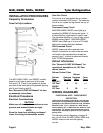
INSTALLATION PROCEDURES
Carpentry Procedures
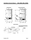
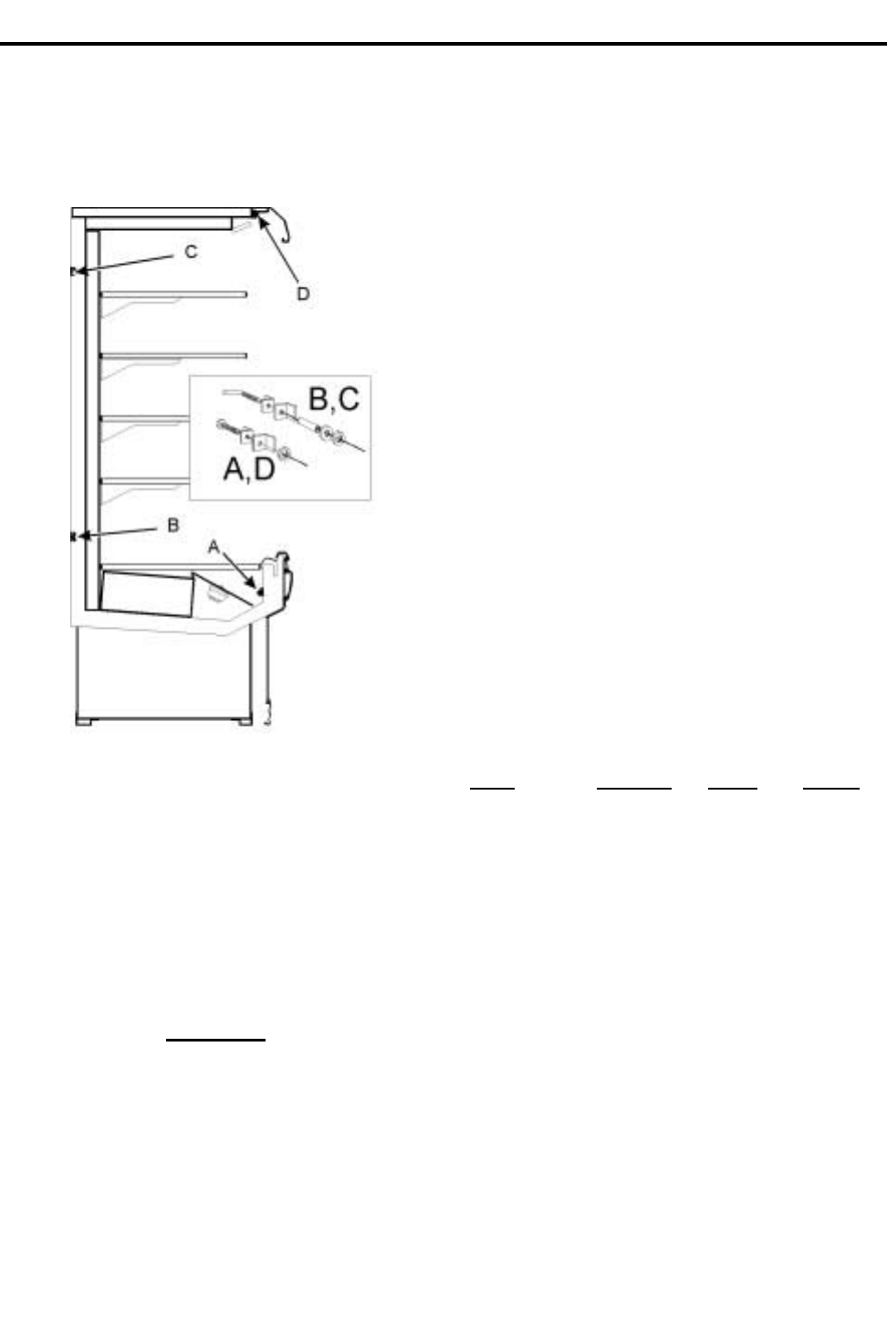
Case Pull-Up Locations
The N5D, N5DH, N5DL and N5DSC models
have four pull-ups at each end of the case.
Pull-ups A, B, C and D are located as shown
and should be install-ed and tightened starting
with A and finishing with D.
See “General-UL/NSF I&S Manual” for line-
up assembly instructions.
Electrical Procedures
Electrical Considerations
CAUTION
Make sure all electrical connections at com-
ponents and terminal blocks are tight.
NOTE
Since the lower front cladding is shipped
loose, the wiring has immediate access.
Case Fan Circuit
This circuit is to be supplied by an uninter-
rupted, protected 120V circuit. The case fan
circuit is not cycled during defrost on any of
these models.
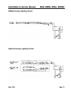
Fluorescent Lamp Circuit
N5D/N5DH/N5DL/N5DSC case lighting is
supplied by 800MA HO horizontal lights. It
is controlled by a light switch in each case.
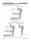
The standard lighting is 1-row of high output
800MA canopy lights. N5D/N5DH/N5DL/
N5DSC also offers up to 4 rows of T-8 shelf
lights with remote electronic ballasts.
Self-Contained Circuit
N5DSC cases are self-contained units.
Specific information on self-contained units,
not listed on the specifications sheets on
pages 6 and 7, should be obtained directly
from TYLER Refrigeration.
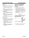
Defrost Information
See “General-UL/NSF I&S Manual” for
operational descriptions for Off Time
defrost control.
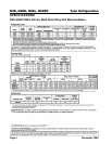
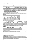
Defrost Control Chart
Defrost
Defrost Defrosts Duration Term.
Type
Per Day (Min) Temp.
N5D(H/L)
Off Time 4 24 -----
N5DSC
Off Time 6 28 -----
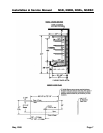
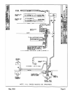
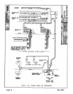
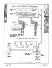
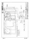
WIRING DIAGRAMS
ELECTRICIAN NOTE - OVERCURRENT
PROTECTION
120V circuits should be protected by 15 or 20 Amp
devices per the requirements noted on the cabinet
nameplate or the National Electrical Code, Canadian
Electrical Code - Part 1, Section 28. 208V defrost
circuits employ No. 12 AWG field wire leads for field
connections. On remote cases intended for end to
end line-ups, bonding for ground may rely upon the
pull-up bolts.
The following wiring diagrams on pages 9
thru 14 will cover the N5D, N5DH, N5DL and
N5DSC case circuits and the lighting
circuits.