


NOTE: DIAGRAMS & ILLUSTRATIONS ARE NOT TO SCALE.
28
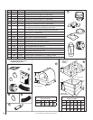
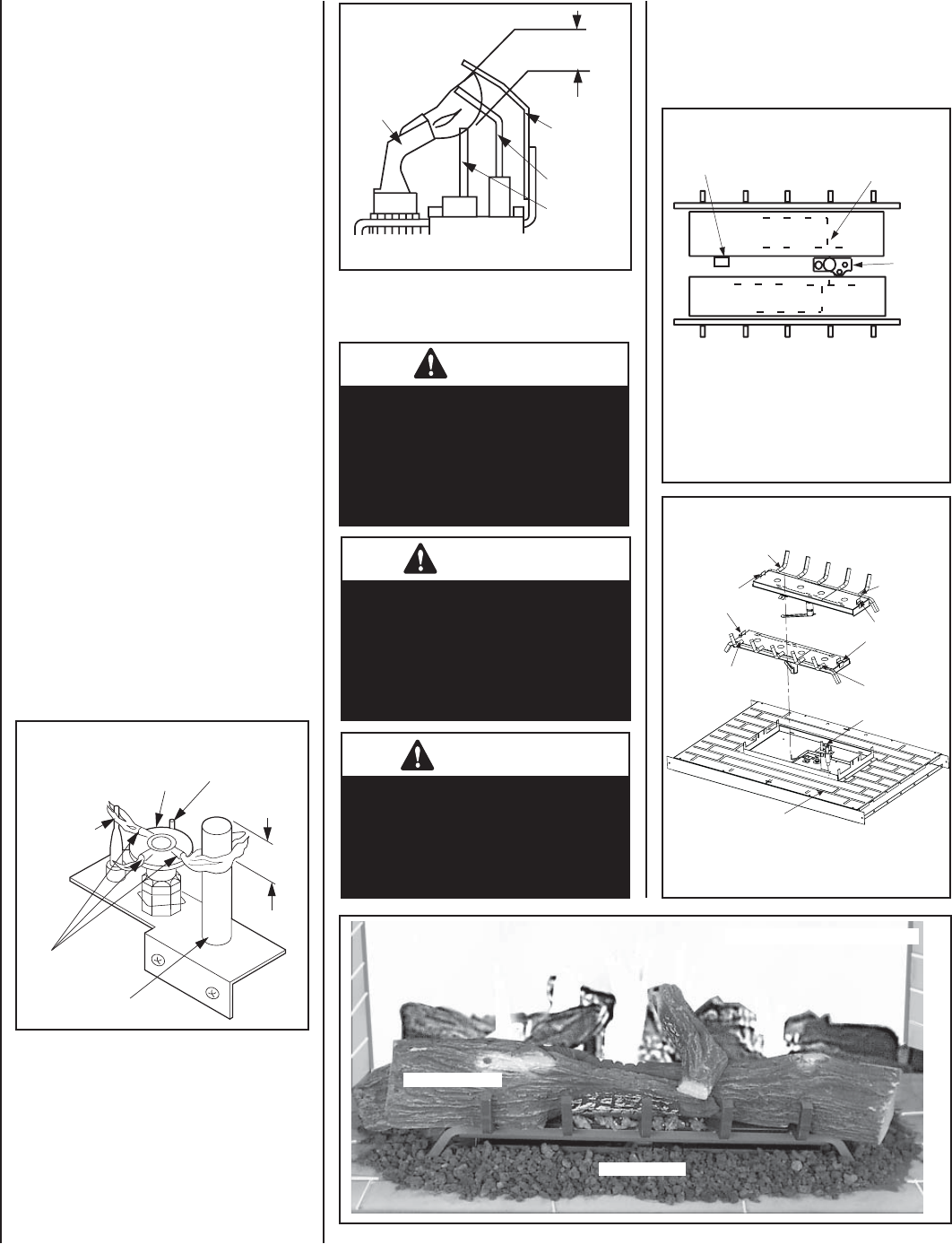
Step 8. INSTALLING LOG SET, VOLCANIC
STONE AND GLOWING EMBERS
WARNING
Logs get very hot and will remain
hot up to one hour after gas supply
is turned off. Handle only when
logs are cool. Turn off all elec-
tricity to the appliance before you
install grate and logs.
WARNING
This appliance is not designed to
burn wood. Any attempt to do so
could cause irreparable damage
to the appliance and prove haz-
ardous to your safety.
WARNING
DO NOT attempt to install logs
until the appliance installation
has been completed, the gas line
connected and tested for leaks
and the initial burner operation
has been checked out.
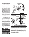
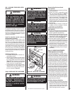
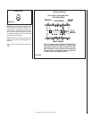
Figure 50
Electronic Appliance Checkout
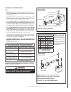
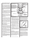
To light the burner, turn ‘ON’ the OFF/ON switch
(located in the control compartment). Ensure the
igniter lights the pilot. The pilot fl ame should
engulf the fl ame rod as shown in Figure 51.
Observe the individual tongues of fl ame on
the burner. Make sure all ports are open and
producing fl ame evenly across the burner. If
any ports are blocked, or partially blocked,
clean out the ports.
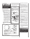
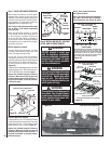
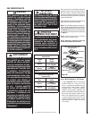
Step 7. CHECK APPLIANCE OPERATION
With the gas line installed, run initial system
checkout before closing up the front of the
appliance. Follow the pilot lighting instructions
provided in the Homeowner's Care and Opera-
tion Instructions. For piezo igniter location see
Figure 48 (millivolt appliances only).
Note: The (pull-out) Lighting instructions label
can be found in the control compartment
(see Figure 48).
When fi rst lighting the appliance, it will take
a few minutes for the line to purge itself of
air. Once purging is complete, the pilot and
burner will light and operate as indicated in
the instruction manual. Subsequent lightings
of the appliance will not require such purging.
Inspect the pilot fl ame.
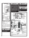
Millivolt Appliance Checkout
The pilot fl ame should be steady, not lifting
or fl oating. Flame should be blue in color with
traces of orange at the outer edge.
The top 3/8" (10 mm) at the pilot generator
(thermopile) and the top 1/8" min (tip) of the
quick drop out thermocouple should be engulfed
in the pilot fl ame. The fl ame should project 1"
(25 mm) beyond the hood at all three ports
(Figure 50).
To light the burner; rotate the gas valve control knob
counterclockwise to the “ON” position then turn
“ON” the OFF/ON switch (installed at Step 4).
Observe the individual tongues of fl ame on
the burner. Make sure all ports are open and
producing fl ame evenly across the burner. If
any ports are blocked, or partially blocked,
clean out the ports.
Figure 51
3/8" to 1/2"
(9 -13 mm)
Ground
Electrode
Flame Rod
Hot Surface
Igniter
Proper Flame
Adjustment
Pilot
Nozzels
ELECTRONIC
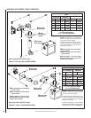
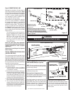
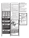
Figure 52
FRONT OF FIREPLACE
REAR BURNER
FRONT BURNER
Outer Log
Notch Location
FIREBOX SUBFLOOR
Outer Log
Notch Location
Outer Log
Notch Location
Outer Log
Notch Location
Riser - Inner Log
Notch Location
LOG NOTCH LOCATION RELATIVE TO BURNER
Pilot Assembly
Riser - Inner Log
Notch Location
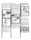
NOTE: INSTALL REAR BURNER FIRST,
THEN FRONT BURNER.
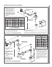
Figure 54
REAR BURNER
FRONT BURNER
PILOT
BURNER
Note: The burners are not identical. Position them so
that the circular burner ports run as shown. Note
especially the vertical run of ports relative to the pilot
burner. Bracket A on the rear burner will interfere
with the pilot burner if an attempt is made to install
the rear burner in the front burner’s position.
BRACKET A
BURNER
PORTS
NOTE: INSTALL REAR BURNER FIRST,
THEN FRONT BURNER.
Burner / Grate Location Reference
(see Figures 53 & 54)
Figure 53
Volcanic Stone
Unitized Log Set
Note: If the burners have been removed for
any reason, rear burner must be installed
before front burner. See Figures 53 and 54.
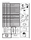
Proper Burner Flame Appearance
Thermocouple
Thermopile
Pilot
Nozzels
SIT MILLIVOLT PILOT ASSEMBLY
Igniter Rod
Hood
Proper Pilot Flame Appearance
3/8" Min.
(9 mm)