


Installer’s Guide
18-CD21D1-5 23
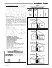
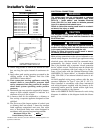
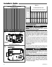
INSTRUCTIONS TO THE OWNERS
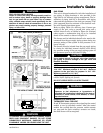
In the event that electrical, fuel, or mechanical
failures occur, the owner should immediately
turn the gas supply off at the manual gas valve,
located in the burner compartment (See Figure
24). Also turn off electrical power to the furnace
and contact the service agency designated by
your dealer.
▲
WARNING
!
Should overheating occur, or the gas supply fail to
shut off, shut off the gas valve to the unit before shut-
ting off the electrical supply.
Failure to follow this warning could result in property
damage, personal injury or death.
▲
WARNING
!
The following warning complies with State of California law, Proposition 65.
This product contains fiberglass wool insulation!
Fiberglass dust and ceramic fibers are believed by the
State of California to cause cancer through inhalation.
Glasswool fibers may also cause respiratory, skin, or
eye irritation.
PRECAUTIONARY MEASURES
● Avoid breathing fiberglass dust.
● Use a NIOSH approved dust/ mist respirator.
● Avoid contact with the skin or eyes. Wear long-
sleeved, loose-fitting clothing, gloves, and eye
protection.
● Wash clothes separately from other clothing: rinse
washer thoroughly.
● Operations such as sawing, blowing, tear-out, and
spraying may generate fiber concentrations requiring
additional respiratory protection. Use the appropriate
NIOSH approved respirator in these situations.
FIRST AID MEASURES
Eye Contact – Flush eyes with water to remove dust. If
symptoms persist, seek medical attention.
Skin Contact – Wash affected areas gently with soap
and warm water after handling.
OPERATING INFORMATION
FLAME ROLL-OUT DEVICE
All models are equipped with a thermal control device
on the burner cover. In case of flame roll-out, the device
will cause the circuit to open which shuts off all flow of
gas.
ABNORMAL CONDITIONS
1. EXCESSIVE COMBUSTION VENT PRESSURE OR
FLUE BLOCKAGE
If pressure against the induced draft blower outlet
becomes excessive, the pressure switch will shut off
the gas valve until acceptable combustion pressure
is again available.
CONTROL AND SAFETY SWITCH
ADJUSTMENT
LIMIT SWITCH CHECK OUT
The limit switch is a safety device designed to close the
gas valve should the furnace become overheated. Since
proper operation of this switch is important to the
safety of the unit, it must be checked out on initial
start up by the installer.
To check for proper operation of the limit switches, set
the thermostat to a temperature higher than the indi-
cated temperature to bring on the gas valve. Restrict
the airflow by blocking the return air or by disconnect-
ing the blower. When the furnace reaches the maxi-
mum outlet temperature as shown on the rating plate,
the burners must shut off. If they do not shut off after a
reasonable time and overheating is evident, a faulty
limit switch is probable and the limit switch must be re-
placed. After checking the operation of the limit control,
be sure to remove the paper or cardboard from the re-
turn air inlet, or reconnect the blower.
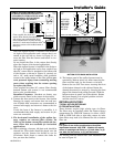
AIRFLOW ADJUSTMENT
Check inlet and outlet air temperatures to make sure
they are within the ranges specified on the furnace rat-
ing nameplate. If the airflow needs to be increased or
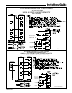
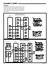
decreased, see the wiring diagram for information on
changing the speed of the blower motor.
▲
WARNING
!
Disconnect power to the unit before removing the
blower door.
Failure to follow this warning could result in property
damage, personal injury or death.
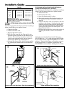
This unit is equipped with a blower door switch which
cuts power to the blower and gas valve causing shut-
down when the door is removed. Operation with the
door removed or ajar can permit the escape of danger-
ous fumes. All panels must be securely closed at all
times for safe operation of the furnace.
NOTE:
Direct drive motors have bearings which are perma-
nently lubricated and under normal use, lubrication is
not recommended.
INDOOR BLOWER TIMING
The control module controls the indoor blower. The
blower starts approximately 45 seconds after ignition.
The FAN-OFF period is approximately 100 seconds
from the interruption of gas flow.
ROOM AIR THERMOSTAT HEAT ANTICIPATOR
ADJUSTMENT
Set the thermostat heat anticipator according to the
current flow measured, or the settings found in the
notes on the furnace wiring diagram (found inside the
furnace casing).