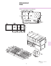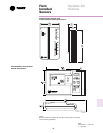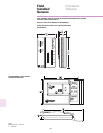
38
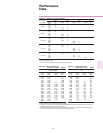
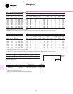
Table 38-2 Approximate Operating Weights Kgs.
Basic Unit Weights
1
Weight of Optional Components
Non- Fact.
Hi-Stat/ 0-25% Inlet Thru-the Fused GFI with
Unit YC YC TC TE Baro. Power Hi Eff. Sup Man Guide Serv base Discon. Discon.
Model Low Heat High Heat Relief Exhaust Fan Motor
2
Damper Econ. Vanes Valves Elec. Switch Switch
**D275 1643 1805 1584 1599 50 74 54 23 117 25 5 3 14 38
**H275 1643 1835 1604 1619 65 90 54 23 128 25 5 3 14 38
**D305 1679 1841 1620 1635 50 74 54 23 117 25 5 3 14 38
**H305 1679 1864 1620 1635 65 90 54 23 128 25 5 3 14 38
**D350 1717 1880 1658 1673 50 74 54 23 117 25 5 3 14 38
**H350 1717 1902 1658 1673 65 90 54 23 128 25 5 3 14 38
**D400 2099 2153 1998 2014 50 74 56 23 131 32 8 3 14 38
**H400 2111 2167 1998 2014 65 90 56 23 135 32 8 3 14 38
**D500 2176 2230 2075 2090 50 74 56 23 131 32 8 3 14 38
**H500 2187 2243 2075 2090 65 90 56 23 135 32 8 3 14 38
Notes:
1. Basic unit weight includes minimum HP Supply Fan Motor.
2. Optional high static and high efficiency motor weights are in addition to the standard motor weight included in the basic unit weight.
Table 38-1 Approximate Operating Weights Lbs.
Basic Unit Weights
1
Weight of Optional Components
Non- Fact.
Hi-Stat/ 0-25% Inlet Thru-the Fused GFI with
Unit YC YC TC TE Baro. Power Hi Eff. Sup Man Guide Serv base Discon. Discon.
Model Low Heat High Heat Relief Exhaust Fan Motor
2
Damper Econ. Vanes Valves Elec. Switch Switch
**D275 3650 4012 3520 3553 110 165 120 50 260 55 11 6 30 85
**H275 3650 4077 3565 3598 145 200 120 50 285 55 11 6 30 85
**D305 3730 4092 3600 3633 110 165 120 50 260 55 11 6 30 85
**H305 3730 4142 3600 3633 145 200 120 50 285 55 11 6 30 85
**D350 3815 4177 3685 3718 110 165 120 50 260 55 11 6 30 85
**H350 3815 4227 3685 3718 145 200 120 50 285 55 11 6 30 85
**D400 4665 4785 4440 4475 110 165 125 50 290 70 18 6 30 85
**H400 4690 4815 4440 4475 145 200 125 50 300 70 18 6 30 85
**D500 4835 4955 4610 4645 110 165 125 50 290 70 18 6 30 85
**H500 4860 4985 4610 4645 145 200 125 50 300 70 18 6 30 85
Notes:
1. Basic unit weight includes minimum HP Supply Fan Motor.
2. Optional high static and high efficiency motor weights are in addition to the standard motor weight included in the basic unit weight.
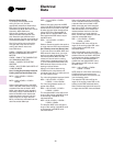
Weights
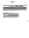
Table 38-3 Point Loading Percentage of Total Unit Weight
1
POINT LOADING - % OF TOTAL UNIT WEIGHT
ABCDEF
21 23 12 16 17 12
1. Point Loading is identified with corner A being the corner with the compressors. As you
move clockwise around the unit as viewed from the top, mid-point B, corner C, corner D,
mid-point E and corner F.
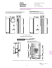
Table 38-4 Minimum Operating Clearances for Unit Installation
Condenser Coil
2
Service Side
Econo / Exhaust End End / Side Access
Single Unit
1
6 Feet (1.82 M) 8 Feet / 4 Feet (2.43/1.21 M) 4 Feet (1.21 M)
Multiple Unit
1,3
12 Feet (3.65 M) 16 Feet / 8 Feet (4.87/2.43 M) 8 Feet (2.43 M)
Notes:
1. Horizontal and Downflow Units, all sizes.
2. Condenser coil is located at the end and side of the unit.
3. Clearances on multiple unit installations are distances between units.
DE F
CB A
TOP VIEW
OF UNIT
COMPRS


