RLC-PRC006-EN22
Trane air-cooled Series R chiller
performance is rated in accordance with
the ARI Standard 550/590-1998
Certification Program. Chiller selection
assistance and performance information
can be obtained by using the Series R
chiller selection program, available
through local Trane sales offices.
The chiller capacity tables cover the
most frequently encountered leaving
liquid temperatures. The tables reflect a
10°F [5.6°C] temperature drop through
the evaporator. For other temperature
drops, apply the appropriate
Performance Data Adjustment Factors
from Table A-1. For chilled brine
selections, contact your local Trane sales
engineer. To select a Trane air-cooled
Series R
™
chiller, the following
information is required:
1
Design load in tons of refrigeration
2
Design chilled water temperature drop
3
Design leaving chilled water temperature
4
Design ambient temperature
Evaporator flow rates can be determined
by using the following formulas:
GPM = (Tons x 24) / Temperature Drop
(Degrees F)
OR
L/S = (kW (Capacity) x .239) /
Temperature Drop (Degrees C)
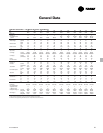
NOTE: Flow rates must fall within the
limits specified in Tables G-1 through G-4
(for GPM or for L/s).
Selection
Procedure
Selection Example
Given:
Required System Load = 140 Tons
Leaving Chilled Water Temperature
(LCWT) = 44°F Chilled Water
Temperature Drop = 10°F Design
Ambient Temperature = 95°F
Evaporator Fouling Factor = 0.0001
1
To calculate the required chilled water
flow rate we use the formula given
below:
GPM = (140 Tons x 24) / 10°F = 336 GPM
2
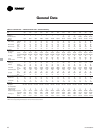
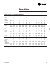
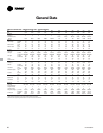
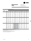
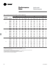
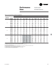
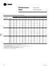
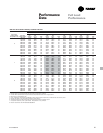
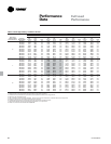
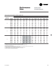
From Table P-1 (RTAC performance
data), an RTAC 140 standard at the given
conditions will produce 138.2 tons with
compressor power input of 158.6 kW
and a unit EER of 9.7.
3
To determine the evaporator pressure
drop use the flow rate (GPM) and
pressure drop chart on page 16. Entering
the curve at 336 gpm, the pressure drop
for a nominal 140 standard evaporator is
16 feet.
Minimum Leaving Chilled Water
Temperature Setpoint
The minimum leaving chilled water
temperature setpoint for water is 40°F.
For those applications requiring lower
setpoints, a glycol solution must be
used. Contact the local Trane sales
engineer for additional information.
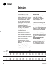
Table S-1. Performance data adjustment factors
Chilled Elevation
Fouling Water Sea Level 2000 ft 4000 ft 6000 ft
Factor Temp. CAP GPM KW CAP GPM KW CAP GPM KW CAP GPM KW
0.0001 8 0.997 1.246 0.999 0.987 1.233 1.012 0.975 1.217 1.027 0.960 1.200 1.045
10 1.000 1.000 1.000 0.989 0.989 1.013 0.977 0.977 1.028 0.963 0.963 1.047
12 1.003 0.835 1.001 0.992 0.826 1.014 0.979 0.816 1.030 0.965 0.804 1.048
14 1.004 0.717 1.002 0.993 0.710 1.016 0.981 0.701 1.031 0.966 0.690 1.049
16 1.006 0.629 1.003 0.995 0.622 1.016 0.982 0.614 1.032 0.968 0.605 1.050
0.00025 8 0.982 1.227 0.991 0.972 1.215 1.003 0.961 1.200 1.018 0.947 1.183 1.036
10 0.986 0.985 0.992 0.975 0.975 1.005 0.963 0.963 1.020 0.950 0.950 1.038
12 0.988 0.823 0.994 0.978 0.815 1.006 0.966 0.805 1.022 0.952 0.793 1.040
14 0.991 0.708 0.995 0.980 0.700 1.008 0.968 0.692 1.023 0.954 0.682 1.041
16 0.992 0.621 0.996 0.982 0.614 1.009 0.970 0.606 1.024 0.956 0.598 1.042


