Caution:
Whenthecustomerisproviding
drivesand/ormotor,theTrane
Companywillnotassumeany
responsibilityfordamages
occurringduetoselected
drivesormotors.
InstallationofMotorand
BeltguardWhenNOT
FactoryInstalled
Arrangement9
1. Removethebeltguardfrom
theshippingposition.Remove
thescrewsontwosidesalong
theedge(thenumbervaries
withthefansize).Lifttheguard
off.
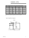
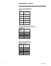
2. Ifneeded,repositionthebelt
tightenertocorrespondtothe
specificbeltlengthandmotor
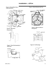
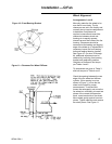
frame(drivecenterline).(See
Figure3).
3. Tomountthemotor,firstturn
theadjustingscrewsforthe
belttightener(anglesorbase
plate)downasfaraspossible.
4. Boltthemotortothebelt
tightener.Beforefinal
tightening,centerthemotoron
thebelttightener.
5. Checkthemotorrotationtobe
surethefanwillrotateinthe
directionshowninFigure4
whenthedriveisinstalled.
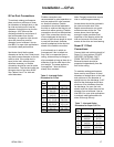
6. Disassemblethebeltguardby
removingtheclipsorscrews
thatholdthefrontandrear
panelstogether.SeeFigure5.
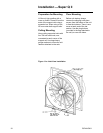
Sliptherearpanelassemblyof
thebeltguardovertheshaftso
thattheshaftprotrudes
throughtherubberblock-offto
beltguard.Onfanssizes
49-60,securetherubber
block-offbyputtingacrimpin
theslotsholdingblock-offto
beltguard.SeeFigure6.
Locatetheedgeoftherear
panelassemblyongasketing
approximately1/4"fromthe
drivehole.RefertoFigure7.
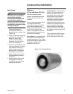
Centertherearpaneloverthe
driveholeintheshelland
securewiththeself-drilling
screwsprovidedasshownin
Figure8.
Arrangement1
Removethemotorpedestal
supportandbeltguardfromthe
topoftheunitandboltthe“F”
shapedpedestalsupporttothe
unitasillustratedinFigure2.
Mountsliderailbasetopedestal.
Boltthemotortothesliderail
base.Disassemblethebeltguard
byremovingtheself-tapping
screws.Sliptherearside
assemblyofthebeltguardover
themotorshaftsothattheshaft
protrudesthroughtherubber
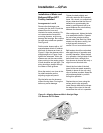
block-off.SeeFigure6.Locatethe
edgeoftherearsideassemblyof
thebeltguardongasketing
approximately1/4"fromtheedge
ofthedriveholeinthefanshell.
Themotorshouldbeascloseto
thefanshaftcenterlineasthe
sliderailbasewillpermit.
Fastenthefrontsideassemblyof
thebeltguardtotherearside
assemblyalreadyinplaceonthe
unitwiththeself-tappingscrews
provided.Thepolyurethane
gasketmustremaininposition
duringthisoperation.Drillpilot
holesintheshellusingthefront
sideassemblyasatemplateand
attachtotheshellwithscrews
provedinFigure8.Attachsupport
legandanglewithscrews
provided.
Installation—QFan
12 QFNA-IOM-1


