


Two-Stage Compressor Widens the Application Range
Why Centrifugal Compressors Surge
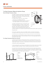
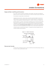
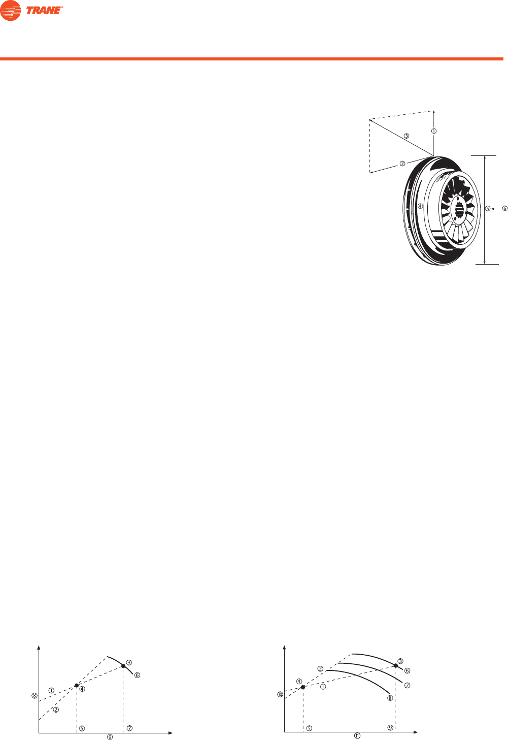
Centrifugal compressors produce their pressure differential
(head) by converting the kinetic energy of the gas leaving
the impeller into static pressure. The velocity of this gas is
the result of two components:
• The radial velocity component V
r
, which is directly
proportional to the refrigerant gas fl ow Q.
• The tangential velocity component V
t
,which is a function of
both impeller diameter D and the rotational speed rpm.
The length of the resultant vector V is proportional to the
kinetic energy available for conversion to static pressure
in the volute. Consequently, for a given compressor, V
t
is
fi xed and V
r
varies with the cooling load. With the chiller
unloading, the pressure differential between evaporator and
condenser decreases. The compressor matches the new load and the lower “head” by closing the
inlet guide vanes.
This reduces the gas fl ow it draws in and modifi es its direction. Component V
r
decreases
accordingly, the vector diagram shifts and at some point, the balance of forces breaks down.
As pressurized gas rushes backwards through the impeller, the pressure in the gas passages
falls, allowing the compressor to restore the balance of forces. If the process repeats itself, the
compressor is said to surge.
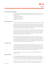
Two-Stage Compressors Surge Less and Later
To produce the same head as a single-stage compressor, two-stage machines use two small
diameter impellers. Component V
t
is the same as on each stage, though V
r
is the same as on a
single-stage compressor. This results in a better balance of forces at low loads and produces a
machine with a wider unloading capability.
In Trane centrifugal chillers, gas prerotation vanes ahead of the compression stage improve impeller
aerodynamic effi ciency, resulting in smoother unloading and reducing power consumption.
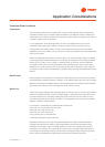
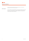
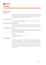
The curves show that two-stage compressors surge less and later than single-stage machines.
Intersection point B, when the load line meets the surge area, corresponds to a higher part load
for the single-stage compressor than would be the case with a two-stage compressor. Two stage
machines, therefore, have a wider range of applications.
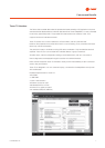
1 - Load Line
2 - Surge Line
3 - A
4 - B
5 - 40%
6 - 90° Vanes
7 - 100%
8 - Compressor Head
9 - Refrigerant Gas Flow
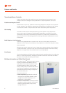
1 - V
r
= f (Q)
2 - V
t
= f (D, RPM)
3 - V = Resultant
4 - rpm
5 - D
6 - Q
Typical single-stage compressor
performance curve
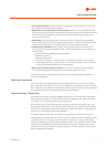
1 - Load Line
2 - Surge Line
3 - A
4 - B
5 - 20%
6 - 90°
7 - 80°
8 - 70° Vanes
9 - 100%
10 - Compressor Head
11 - Refrigerant Gas Flow
Typical two-stage compressor
performance curve
10
Features and Benefi ts
CTV-PRC001-E4