


|nsta||er's Guide
H. OPERATIONAL AND CHECKOUT
PROCEDURES
Final phases of this installation are the unit Operational and
Checkout Procedures which are found in this instruction on
page 8. To obtain proper performance, all units must be
operated and charge adjustments made in accordance with
procedures found in the Service Facts.
I. ELECTRIC HEATERS
Electric heaters, if used, are to be installed in the air han-
dling device according to the instructions accompanying the
air handler and the heaters.
J. START CONTROL
Some models have quick start components which are factory
installed. For models that do not have factory installed start
components, provisions are made for a field installed start kit
accessory. When adding an accessory, follow the instructions
provided with the kit.
K. OUTDOOR THERMOSTAT
An outdoor thermostat TAYSTAT250A may be field installed.
For data, see wiring diagram attached to unit and instruction
sheet packaged with outdoor thermostat.
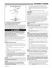
L. SEACOAST SALT SHIELD
All units are shipped with a black Seacoast Salt Shield
attached to the access panel. Removal of the shield -will
potentially shorten the life of the joints in the outdoor coil.
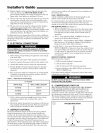
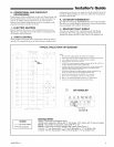
T'STAT
TYPICAL FIELD HOOK=UP DIAGRAM
VAR}AB/E SPEED
AIR HANDLER
NO]E 8
.......................................
See
Note A
PRINT D FROM D 54050P01
2 STAGE
I
HAT PUMP
R
ODTA
B
BR
....... (I)
0
Notes:
1. Be sure power supply agrees with equipment nameplate.
2. Power wiring and grounding of equipment must comply with local codes.
3. Low voltage wiring to be No. 18 AWG minimum conductor.
4. ODT-B must be set lower than ODT-A.
5. If ODT-B is not used, connect A Jumper wire from W3 to W2. If ODT-A is
not used, connect a jumper wire from W2 to W1.
6. If electric heat does not have 3rd contactor (CH), connect ajumper wire
from W3 to W2. If electric heat does not have 2nd contactor (BH),
connect ajumper wire from W2 to W1.
7. X2 must be connected to variable speed air handler terminal W3, as
shown, for proper indoor air flow during the defrost cycle.
8. Be sure the jumper between R and BK is cut or removed.
9. With O and Y/Y2 energized, indoor fan is at 80% airflow.
10. With O, Y/Y2 and BK energized, indoor fan is at 100% airflow.
11. Connect only if used with applicable indoor thermostat.
(_) AIR HANDLER
G O B W3 W2 W!
[] [] [] [] [] []
e []_[]T Y YIo oi
_'dumper
See Note B
LEGEND
..... FACTORY WIRING
_ FIELD WIRING
REQUIRED WIRING
Refer to Field Hook-up Diagrams above.
4TWX6 units require 80% airflow with Y1 (first stage), 100% airflow with Y2 (second stage).
Note A - The installer must jumper at the L_/q-B"R" to "O".
Note El- Cut/remove the factory installed "BK" jumper (See Figure 1).
Connect "YI" from thermostat to "Y!Y2" at VS Airhandler to "Y1" at Outdoor Unit.
Connect "Y2" from thermostat to "BK" at VS Airhandler to "Y2" at Outdoor Unit.
18-BC55D1-2 5