


18-BC51D3-2 5
Installer’s Guide
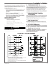
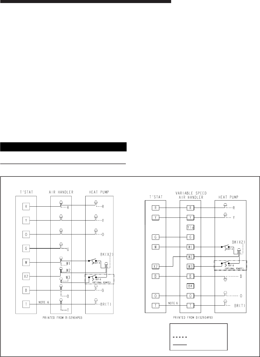
TYPICAL FIELD HOOK-UP DIAGRAMS
Notes:
1. Be sure power supply agrees with equipment nameplate.
2. Power wiring and grounding of equipment must comply with local codes.
3. Low voltage wiring to be No. 18 AWG minimum conductor.
4. ODT-B must be set lower than ODT-A.
5. If outdoor thermostats (ODT) are not used, connect W1 to W2 and W3.
6. N/A to programmable thermostat.
LEGEND
FACTORY WIRING
FIELD WIRING
In normal operation, the defrost control light will flash once
each second. If the light is flashing more than once per
second or not at all, refer to the service manual for that unit.
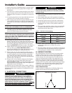
PIN IDENTIFICATION (See Figure 7.)
1. TEST_COMMON (Shorting any of the other pins to this
pin causes the function of the other pin to be executed.
Leaving this pin open results in the normal mode of
operation.)
2. TST = Test (Shorting TEST_COMMON to this pin
speeds up all defrost board timings.)
3. FRC_DFT = Forced Defrost (Short TEST_COMMON to
this pin for two (2) seconds to initiate a forced defrost.
Remove the short after defrost initiates.)
DEFROST CONTROL CHECKOUT
Normal operation requires:
a. LED on board flashing 1 time/second.
b. 24V AC between R & B
c. 24V AC between Y & B with unit operating
d. Defrost initiation when FRC_DFT pin is shorted to
TEST_COMMON pin.
If a defrost control problem is suspected, refer to the service
information in control box.
▲
WARNING
!
Do NOT connect 24 VAC to T1 (ODS-A) terminal. ODS-A
thermistor WILL BE BLOWN.
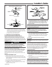
H. COMPRESSOR START UP
After all electrical wiring is complete, SET THE THERMO-
STAT SYSTEM SWITCH IN THE OFF POSITION SO
COMPRESSOR WILL NOT RUN, and apply power by closing
the system main disconnect switch. This will activate the
compressor sump heat (where used). Do not change the
Thermostat System Switch until power has been applied for
one (1) hour. Following this procedure will prevent potential
compressor overload trip at the initial start-up.
I. OPERATIONAL AND CHECKOUT
PROCEDURES
Final phases of this installation are the unit Operational and
Checkout Procedures which are found in this instruction on
page 8. To obtain proper performance, all units must be
operated and charge adjustments made in accordance with
procedures found in the Service Facts.
J. ELECTRIC HEATERS
Electric heaters, if used, are to be installed in the air han-
dling device according to the instructions accompanying the
air handler and the heaters.
K. OUTDOOR THERMOSTAT
An outdoor thermostat TAYSTAT250B may be field installed.
For data, see wiring diagram attached to unit and instruction
sheet packaged with outdoor thermostat.
L. SEACOAST SALT SHIELD
BAYSEAC001 (Seacoast Kit) is available for application on
units installed within one mile of salt water including
seacoasts and inland waterways.