


– 121 –
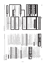
Sound-insulation plate
Sound-insulation plate
(upper)
(upper)
Sound-insulation plate
Sound-insulation plate
(rolling out)
(rolling out)
Sound-insulation plate
(upper)
Sound-insulation plate
(rolling out)
Compressor lead
Compressor lead
Inverter
Inverter
assembly
assembly
Hook
Hook
Case thermostat
Case thermostat
Compressor lead
Partition plate
Partition plate
Inverter
assembly
Inverter
Inverter
assembly
assembly
Inverter
assembly
Hook
Partition plate
Case thermostat
Fan-IPDU board
Fan-IPDU board
Remove the fan motor lead wire
Remove the fan motor lead wire
from the cord clamp.
from the cord clamp.
Remove the fan motor lead wire
from the cord clamp.
Remove the fan motor lead wire
Remove the fan motor lead wire
from the cord clamp.
from the cord clamp.
Remove the fan motor lead wire
from the cord clamp.
Discharge port
Discharge port
cabinet
cabinet
Discharge port
cabinet
Interface board
Interface board
Interface board
Fan-IPDU board
Cut the
Cut the
banding band
banding band
Cut the
banding band
Cut the
Cut the
banding band
banding band
Cut the
banding band
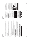
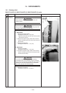
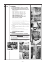
No.
4
Part name
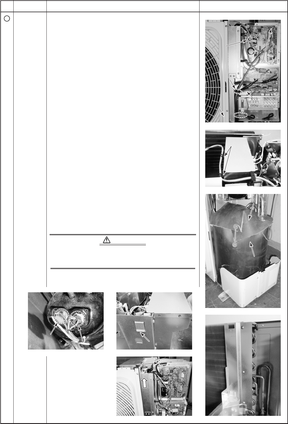
Inverter
assembly
Procedure
1. Detachment
1) Carry out the operation in 1. of
Q
, 1. of
S
above.
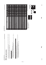
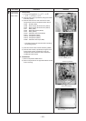
2) Remove the connectors connected to the Fan IPDU
board, the connector connected to other components
from the control board
(Interface board).
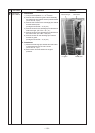
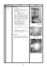
CN600: TS sensor (3P: White, tube: Gray)
CN601: TE sensor (2P: White, tube: Blue)
CN602: TO sensor (2P: Yellow, tube: Black)
CN603: TD sensor (3P: White, tube: Red)
CN604: TL sensor (2P: White, tube: White)
CN609: Case thermo. (2P: Blue)
CN690: High poressure switch (3P: Green)
CN700: 4-way coil (3P: Yellow)
CN710: PMV coil (6P: White)
• Fan IPDU board
CN700: Outdoors lower fan motor (3P: Blue)
CN750: Outdoors upper fan motor (3P: White)
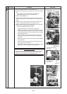
Cut the banding band and remove connector connected
from fan motor to fan motor relay board.
∗ Remove connectors after unlocking housing section
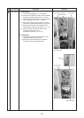
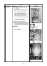
3) Remove the screw (1 position) fixing the discharge port
cabinet.
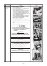
4) Cut bundling band fixing various lead lines to inverter
assembly.
5) Remove sound-insulation plate (upper).
6) Remove terminal cover of compressor and remove
compressor lead.
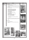
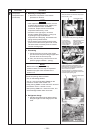
7) Pull up the inverter assembly at upper side to remove
hook of partition plate (rear left part).
2. Attachment
1) Mount the inverter assembly on the partition plate.
CAUTION
When mounting the inverter assembly on the partitioning
plate, ensure proper mounting of the hook (rear left part)
with partitioning plate.
2) Mount the individual components in the opposite
procedure to that during detachment.
Remarks