42
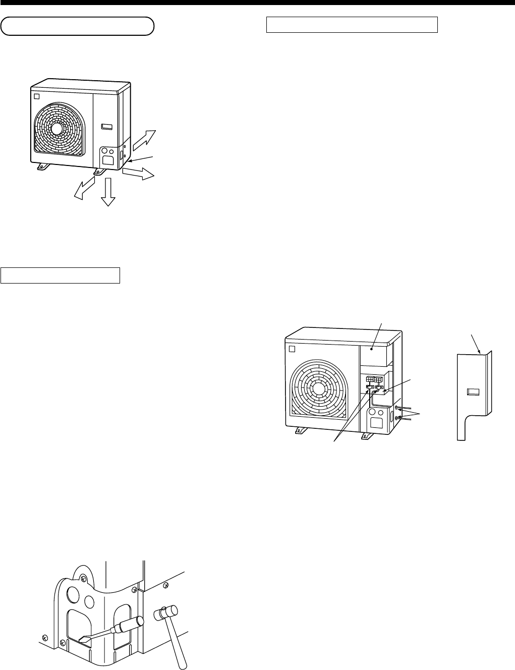
Knockout of Pipe Cover
<SM800AT-E, SP560AT-E, SP800AT-E>
Front direction
Rear direction
Pipe cover
Side direction
Down direction
Knockout procedure
• The indoor/outdoor connecting pipes can be con-
nected to 4 directions.
Take off the knockout part of the pipe cover in which
pipes or wires pass through the base plate.
• As shown in the figure, do not remove the pipe cover
from the cabinet so that the knockout hole can be
easily punched. To knock out, it is easily taken off by
hands by punching a position at the lower side of 3
connected parts with screwdriver along the guideline.
• After marking the knockout hole, remove the burr and
mount the attached protective bush and guard
material for pass-through part in order to protect
pipes and wires.
After connecting the pipes, be sure to mount the pipe
cover. The pipe cover is easily mounted by cutting off
the slit at the lower part of the pipe cover.
How to remove the front panel
1. Remove screws of the front panel.
2. Pull the front panel downward.
Removing the front panel, the electric parts appear at
the front side.
• The metal pipes are attachable to the piping holes.
If the size of the used power pipe does not match
with the hole, adjust the hole size to match with pipe
size.
• Be sure to fix the power cable and indoor/outdoor
connecting cable with bundling band sold on the
market so that they do not make contact with the
compressor and discharge pipe.
(Temperature of the compressor and discharge pipe
becomes high.)
In order to avoid the force applied to on the connect-
ing section, be sure to fix the cables to the cord
clamps provided on the pipe valve fixing plate and the
electric parts box.
Cord clamp
Electric parts box
Front panel
Pipe valve
fixing plate
Piping
hole
3
SELECTION OF INSTALLATION


