


– 48 –
9. CIRCUIT CONFIGURATION AND CONTROL SPECIFICATIONS
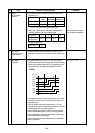
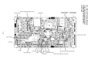
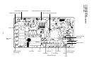
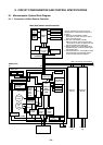
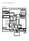
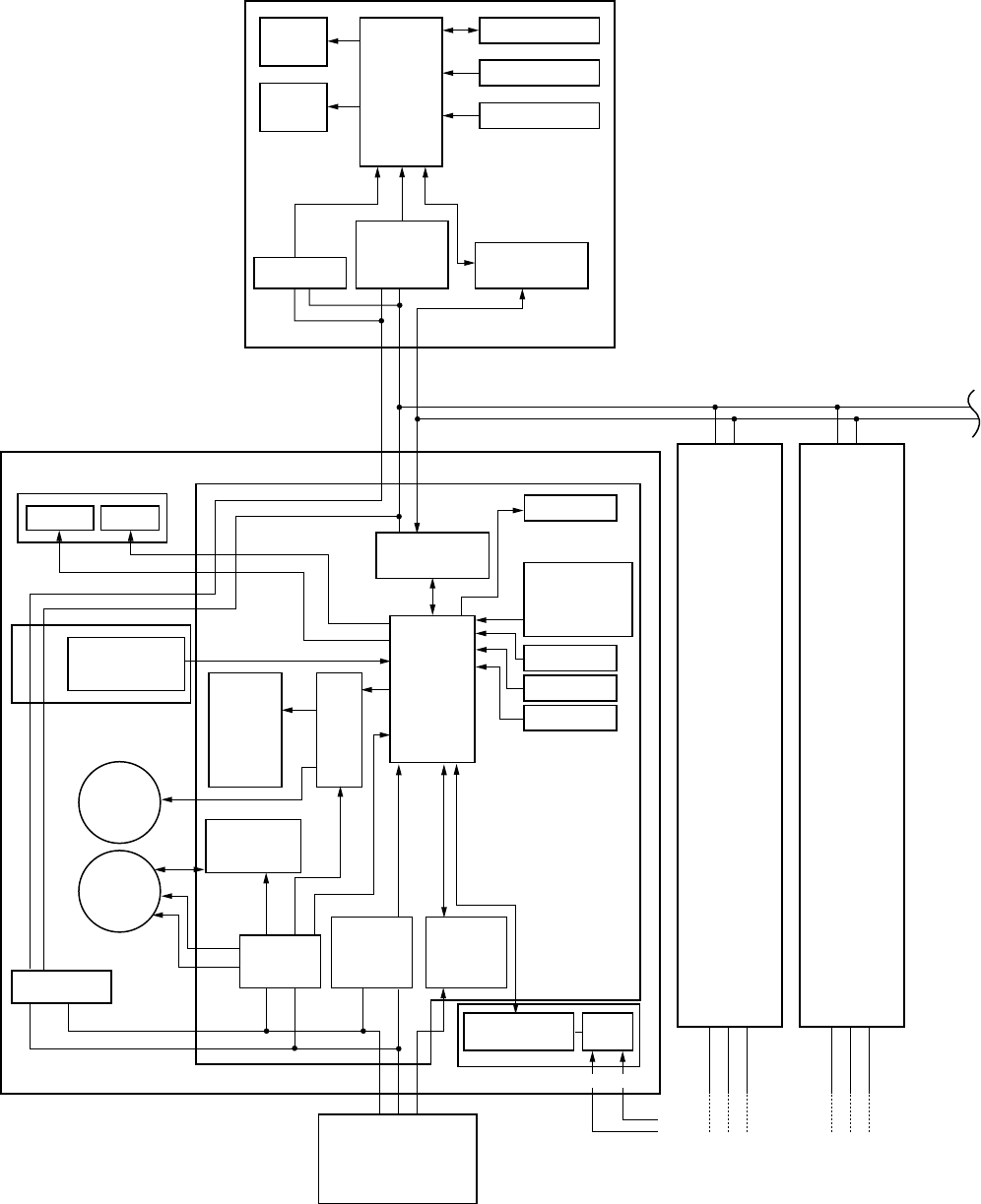
9-1. Microcomputer System Block Diagram
9-1-1. Connection of Main Remote Controller
Main (Sub) master remote controller
Sensor display P.C. board
(MCC-819)
Main P.C. board (MCC-1370A)
Display
LED
CPU
EEPROM
EEPROM
TA sensor
TMP47C
820F
Display
LCD
Function setup
Key switch
Sensors LED
TA shift setup
Model selection
Function setup
Remote controller
No. setupTwin/
Triple setup
Sub P.C. board
(MCC-1370B)
#1
#2
BC
Indoor unit
Optional
output
Comp.
Run
Error
Heat
Power
circuit
DC15V
DC
5V
DC
12V
AC
synchronous
signal input
circuit
Serial
send/
receive
circuit
Communication
LSI
Pulse
trans
Indoor fan
control circuit
Driver
CPU
Serial send/
receive circuit
Serial send/
receive circuit
AC
synchronous
signal input
circuit
TMP87CM
40AN
(TMP87PM
40AN)
TC sensor
TCJ sensor
Louver
motor
Indoor
fan
motor
Transformer
XY
Communication P.C. board (Option)
MCC-1337
Outdoor unit
123
123
DC310~340V
Power circuit
ABC
ABC
123
Outdoor
unit
Same as
the left
#3
BC
123
Outdoor
unit
Same as
the left
Max. 16 units are connectable.
The P.C. boards of the indoor unit are
classified into 4 boards according to the
function.
1. Main P.C. board (MCC-1370A)
Controller for power circuit, fan motor
driver, and whole unit
2. Sub P.C. board (MCC-1370B)
Setup of unit No. and concurrent twin
* The sub P.C. board is located near the
remote controller terminal block.
3. Sensor display P.C. board (MCC-819)
Wireless remote controller receive part,
LED display part
4. Communication P.C. board (MCC-1337)
Communication part with the central
control remote controller (Option)