– 122 –
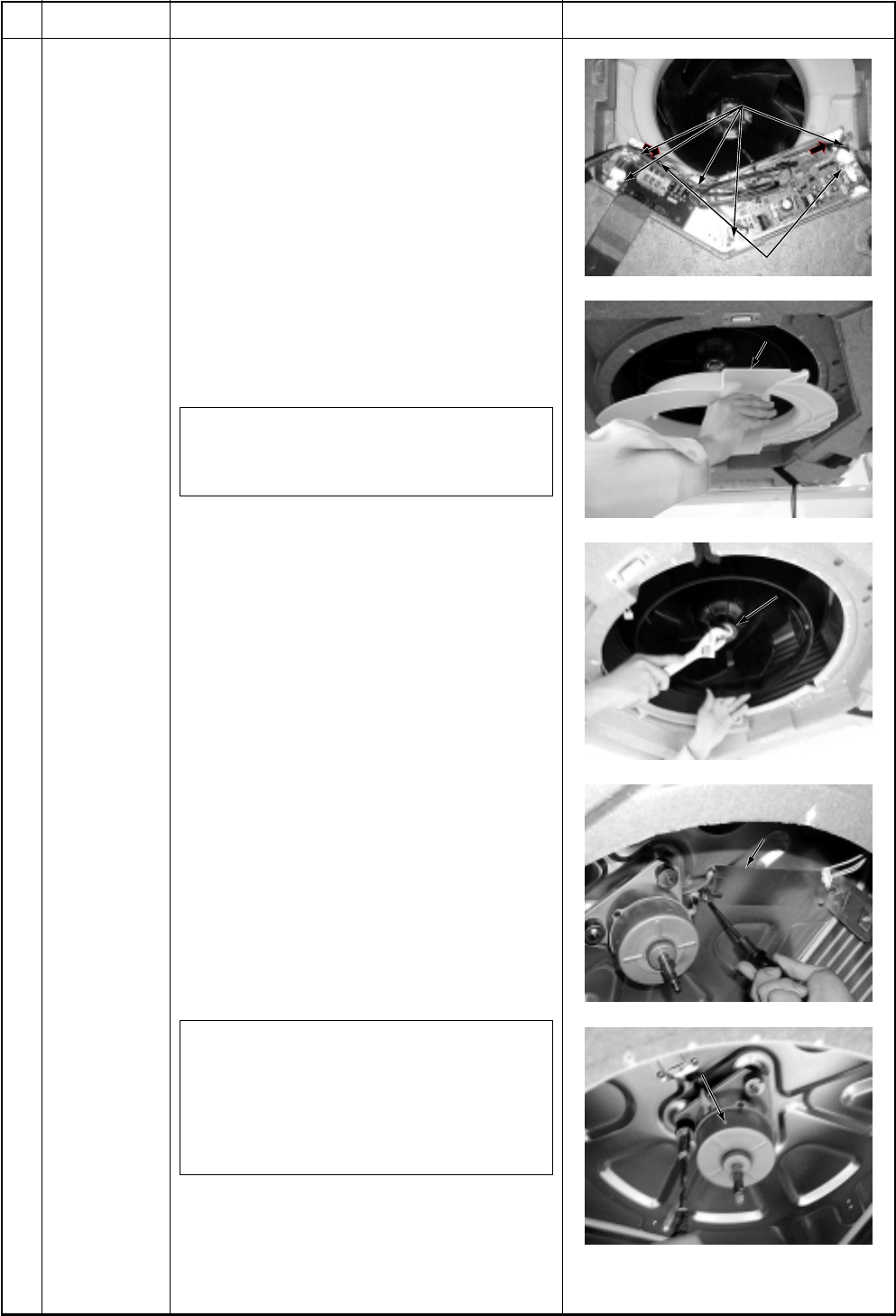
Screws fixing earth lead wires
Screws fixing electric parts box
Bell mouth
Turbo fan
Motor lead holder
Motor lead holder
Fan motor
an motor
Screws fixing earth lead wires
Screws fixing electric parts box
Bell mouth
Turbo fan
Motor lead holder
Fan motor
No.
Part name
Fan motor
Procedure
1. Detachment
1) Perform works of items 1 of and 1 of
.
2) Remove clamps of the lead wires
connected to the following connectors of
the control P.C. board.
CN33 : Louver motor (5P: White)
CN34 : Float switch (3P: Red)
CN68 : Drain pump (3P: Blue)
CN101 : TC sensor (2P: Black)
CN102 : TCJ sensor (2P: Red)
CN333 : Power supply of fan motor
(5P: White)
CN334 : Position detection of fan motor
(5P: White)
NOTE :
Remove the connector by releasing locking
of the housing.
3) Remove screws fixing earth lead wire in
the electric parts box. (Ø4 × 6, 2 pcs.)
4) Remove indoor/outdoor inter-unit cable
and remote controller cable of the
terminal block.
5) Remove screws fixing the electric parts
box. (Ø4 × 10, 5 pcs.)
6) Remove screws fixing the bell mouth.
(Ø4 × 10, 6 pcs.)
7) Remove nuts fixing the turbo fan.
(M6, 1 pc.)
8) Remove screws fixing holder of the
motor lead wires to remove the motor
lead wires from the clamp. (Ø4 × 8, 3
pcs.)
9) Remove nuts fixing the fan motor to
remove it.
2. Attachment
1) Fix the parts, fan motor, holder of the
motor lead, turbo fan, bell mouth, and
electric parts box successively to their
original positions.
NOTE 1 :
When fixing the turbo fan, be sure to match
the fan boss with D-cut of the motor shaft.
NOTE 2 :
Fix the turbo fan with torque wrench
5.9 ± 0.6Nm.
2) Connect connectors, earth lead wire,
indoor/outdoor inter-unit cable, and
remote controller cable which have been
disconnected in the above item 1 as
before.
Remarks


