


– 119 –
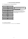
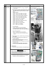
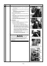
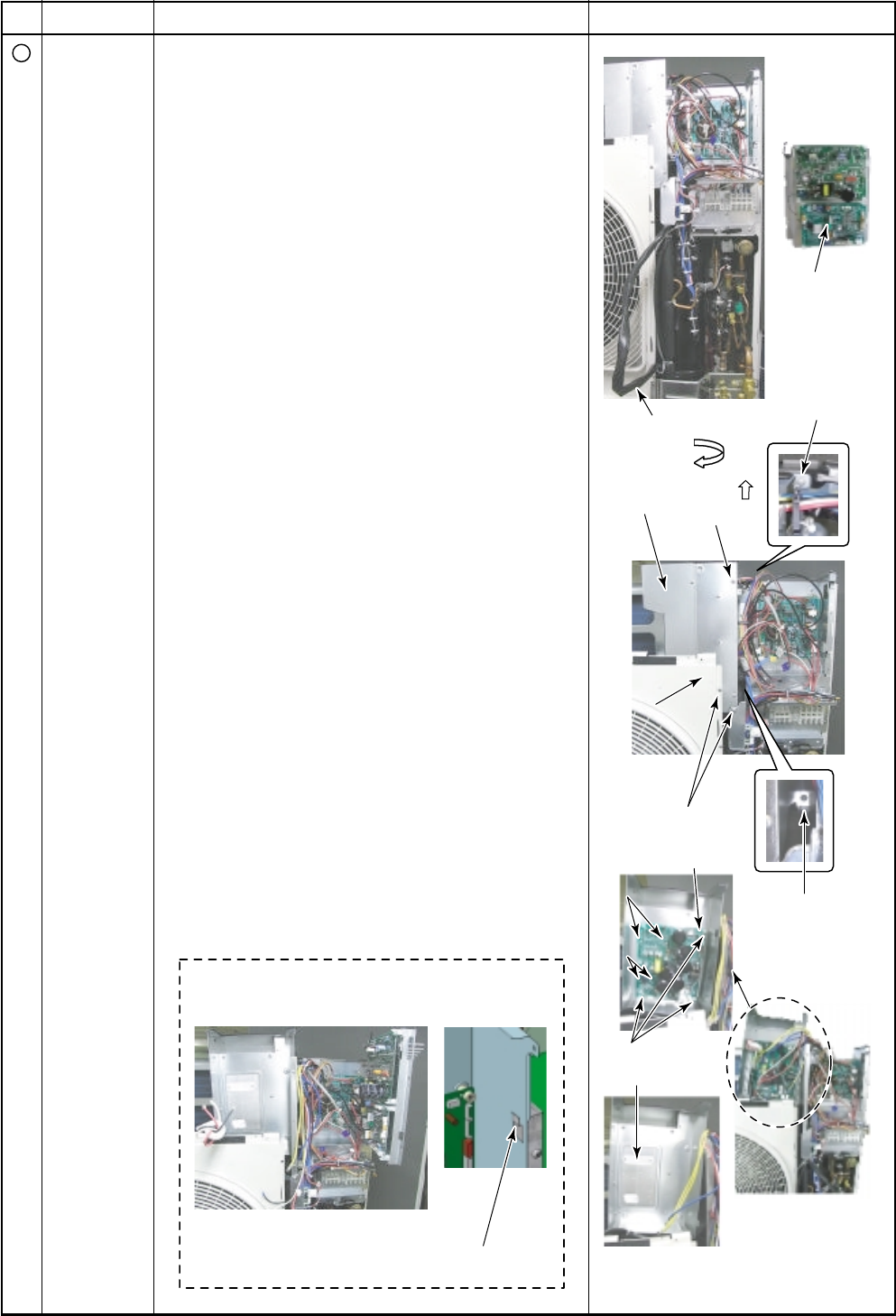
Temporary suspended state
of Inverter Assembly (IPDU)
Using the hook,
it is possible to temporarily suspend
the inverter assembly (IPDU).
Inverter assembly
Inverter assembly
(front)
(front)
Inverter assembly
(front)
Rotate 90˚
Compressor lead
Inverter assembly
(IPDU)
Screw
Compressor
IPDU board
Heat sink
Screws
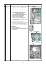
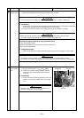
State of compressor IPDU board
when removed
Using the hook
Discharge
Discharge
port cabinet
port cabinet
Discharge
port cabinet
Screws
Screws
Screws
Screws
Screws
Screws
Screws
Screw
Screw
No.
9
Part name
Compressor
IPDU board
MCC-1596
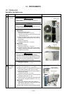
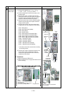
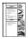
Procedure
1. Detachment
1) Carry out the operation in 1. of
Q
, 1. of
R
,
1. of
T
, 1. of
V
, 1. of
W
and 1. of
X
.
2) Pull the compressor lead from the space in the
partition plate.
3) Remove the screw (1 position) fixing the dis-
charge port cabinet and the screws (4r positions)
fixing the inverter assembly (IPDU) and then
remove the lead wire from the top clamp.
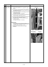
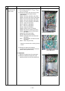
4) Slide and remove the inverter assembly (IPDU),
rotate through 90 degrees and place the base
facing the front surface.
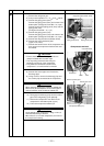
5) Remove the lead wire and connector to other
components from the compressor IPDU board.
CN01: Relay (Red)
CN02: Noise filter board (White)
CN03: Relay (Black)
CN04: Posister (Red)
CN07: Power supply terminal block (Blue)
CN08: Power supply terminal block (Blue)
CN09: Power supply terminal block (Yellow)
CN10: Power supply terminal block (Yellow)
CN201: Compressor (Red)
CN202: Compressor (White)
CN203: Compressor (Black)
CN851: FAN-IPDU board (5P, Red)
CN101: FAN-IPDU board (3P, White)
∗ Connectors should be removed after unlocking
the housing section.
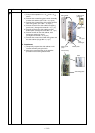
6) Remove the screws (4 positions) fixing the heat
sink and the screws (3 positions) fixing the
compressor IPDU board and then remove the
compressor IPDU board.
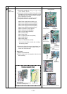
2. Attachment
1) Mount compressor IPDU board.
2) Mount components in the opposite method to that
when removing.
Remarks