– 112 –
14. DETACHMENTS
14-1. Outdoor Unit
RAV-SM224, RAV-SM280 series
No.
1
Part name
Common
procedure
Procedure
WARNING
Stop operation of the air conditioner and turn off
breaker switch.
CAUTION
Ensure wearing of gloves when performing any work
in order to avoid injury from parts, etc.
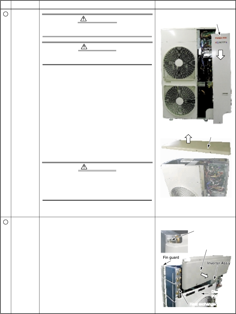
1. Detachment
1) Remove the service panel.
(Hexagonal screws Ø4 × 10, 3 pcs.)
• Remove the screws and then pull service panel
downward to remove.
2) Remove the power supply cable and the indoor/
outdoor connecting wire from the cord clamp and
the terminal.
3) Remove the top plate.
(Hexagonal screws Ø4 × 10, 6 pcs.)
2. Attachment
1) Attach the top plate.
(Hexagonal screws Ø4 × 10, 6 pcs.)
2) Connect the power supply cable and the indoor/
outdoor connecting wire to the terminal and then
fix with the cord clamp.
CAUTION
The power supply cable and the indoor/outdoor
connecting wire must be affixed along the crossover
pipe using a commercially available bundling band so
that they do not make contact with the compressor,
gas valve, gas pipe and discharge pipe.
3) Attach the front panel.
(Hexagonal screws Ø4 ×10, 3 pcs.)
Remarks
Service pane
l
Top plat
e
1. Detachment
1) Carry out the operation in 1. of
Q
above.
2) Remove screws for the discharge port cabinet and
the inverter assembly. (ST1T Ø4 × 8, 2 pcs.)
3) Remove screws for the discharge port cabinet and
the discharge cabinet.
(Hexagonal screw Ø4 × 10, 2 pcs.)
4) Remove screw for the discharge cabinet and heat
exchanger. (ST1T Ø4 × 8, 1 pc.)
5) Remove screw for the discharge port cabinet and
the fin guard. (Hexagonal screw Ø4 × 10, 1 pc.)
2. Attachment
1) Place upper left side of discharge cabinet on
upper side of end board of heat exchanger and fix
with a screw. (ST1T Ø4 × 8, 1 pc.)
2) Mount other removed screws into original positions.
Setting moment
Upper end plate
of heat exchanger
Dischar
g
e port
cabinet (upper)
Discharge
g
b
port cabine
Heat exchanger
2
Discharge
port cabinet
(upper)


