


FILE NO. SVM-07008
– 88 –
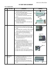
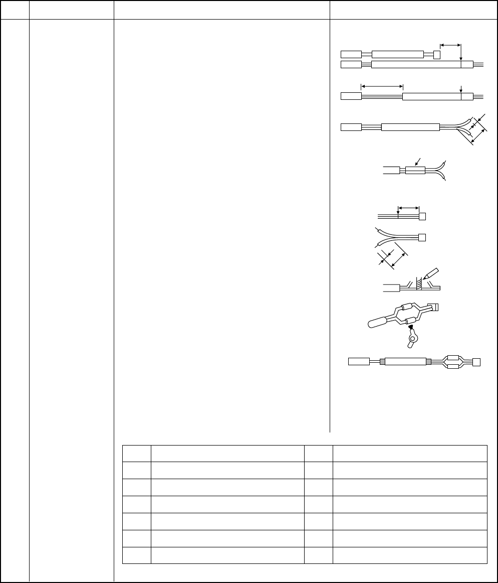
No. Part name Procedures Remarks
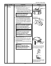
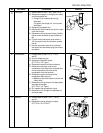
1)
Cut the sensor 100 mm longer than old
one.
2) Cut the protective tube after pulling out it
(200 mm).
3) Move the protective tube toward the
thermal sensor side and tear the tip of
lead wire in two, then strip the covering
part.
4) Pass the stripped part through the ther-
mal constringent tube.
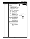
5) Cut the old sensor 100 mm length on the
connector side, and recycle that connector.
6) Tear the lead wire in two on the connector
side and strip and covering part.
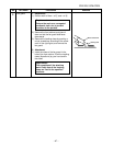
7) Twist the leads on the connector and
sensor sides, and solder them.
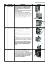
8) Move the thermal constringent tubes
toward the soldered parts and heat them
with the dryer and constring them.
9) Wind the attached color tape round the
both terminals of the protective tube when
colored protective tube is used.
10) Fix the sensor again.
NOTES:
1) Store the joint part of the sensor and the
connector in the electric parts box.
2) Never joint them near the thermal sensor
part. Otherwise, it would cause insulation
inferiority because of dew drops.
3) When replacing the sensor using the
colored protective tube, wind the color
tape matching the color of that tube.
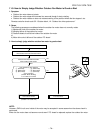
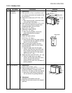
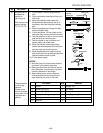
! Replacement of
temperature
sensor for
servicing only
Common service
parts of sensor
TO, TS, TE, TD
These are parts
for servicing
sensors.
Please check
that the accesso-
ries shown in the
right table are
packed.
Part name Q’ty Remarks
1 Sensor 1 Length: 3 m
2 Sensor Spring (A) 1 For spare
3 Sensor Spring (B) 1 For spare
4 Thermal constringent tube 3 Including one spare
5 Color tape 1 9 colors
6 Terminal 3
Cutting here
Cutting here
Thermal
constringent tube
Soldered part
Dryer
Winding the color tape
200
100
15
70
Thermal
sensor part
Connector
Cutting here
100
15
70