


- 13 -
3. Installation
Make sure the location satisfied the requirements listed under Storage and Installation
Location (page 3) and check the dimensions using the diagrams in other catalogs or external
view diagrams and panel cut diagram. Prior to installation, the maximum fault current capacity
of the power system at the point of installation should be verified. This value must not exceed
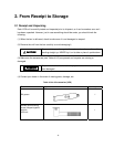
the symmetrical interrupting capability of the circuit breaker. See typical circuit breaker
nameplate below.
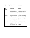
Do not exceed the ratings specified on the breaker nameplate or
system accessories. Underrated equipment can fail during operation
causing fire, explosion, severe injury, death, and property damage.
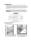
Typical Circuit Breaker Nameplate
3.1 Mounting the Drawout Cell
3.1.1 Mounting in the panel
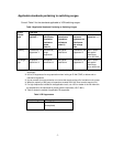
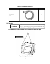
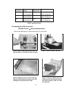
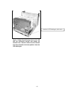
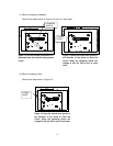
To install the draw-out unit, perform the steps shown in Figures 4 and 5 in that order.
Figure 4 Fasten the drawout cell to the panel with
the 4 hexagonal bolts (M8). Tightening torque
should be 11.8 to 14.7 N-m (120 to 150 kgf-cm).
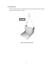
Figure 5 Crimp the crimp-on terminal
provided with the unit to the grounding wire
and use the hexagonal bolt (M8) to fasten it
in place. The tightening torque should be
11.8 to 14.7 N-m (120 to 150 kgf -cm).
DANGER