


Installation Requirements
The following list of installation requirements is provided to assure maximum performance of the Toro PVB. Read
this list completely prior to installation.
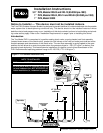
■ The installed height of the PVB, when measured at the Critical Level line, must be at least
12" (30.5cm) above the highest downstream water outlet (sprinkler, hose bib etc.). Refer to
Figure 1 for location of the Critical Level line.
■ Provide an accessible location for periodic inspection and testing of the PVB.
■ The PVB must not be subject to standing water which can rise to less than 6" from the Criti-
cal Level line.
■ Install the PVB vertically with the top of the device in a level position.
■ Do not install the PVB in a valve box below ground level.
■ Do not install the PVB indoors or in an area where some water spillage is harmful.
■ Do not install the PVB until the water supply line has been flushed of foreign material.
■ Do not over-tighten inlet and outlet caps – hand-tight is sufficient.
■ Do not use the PVB with fertilizer injection.
Caution: Do not allow the PVB to freeze or be subjected to downstream water hammer
effect. Thermal water expansion and excessive pressure situations can cause severe
damage to the PVB and the irrigation system.
Caution: Use teflon tape for sealing threaded connections. Use of other sealing com-
pounds may cause thread deterioration.
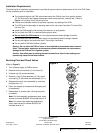
Servicing Float and Check Valves
(Refer to Figure 2)
1. Turn off water supply to PVB at source.
2. Remove three cover screws (1) and cover (2).
3. Unscrew cap (3) counterclockwise.
4. Remove o-ring (4), float assembly (5 & 6), check
valve spring (7), and check valve assembly (8–11).
5. Disassemble check valve assembly by removing
phillips screw (11).
6. Clean and inspect all components thoroughly prior
to reassembly.
7. Reassemble in reverse order, utilizing new parts
as needed.
Note: For float assembly replacement parts, order
service kit number 89-6006. Kit includes items 3–6.
Note: For check valve assembly replacement
parts, order service kit number 80-0553. Kit
includes items 8–11.
MODEL
PVB
M
W
W
P
0
1
5
P
S
I
M
W
W
1
T
5
0
°
F
1 INCH
1
2
7
8
9
10
11
3
6
5
4
Figure 2
Printing Date
June 1997 – Rev. E
Form No.
363-0030
© 1997 THE TORO COMPANY
Irrigation Division
An ISO 9001-Certified Facility
PO Box 489
Riverside, CA 92502 • Printed in U.S.A.
RELEASED Version ©Toro 2006-2006