


NOTE: DIAGRAMS & ILLUSTRATIONS NOT TO SCALE.
7
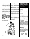
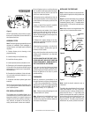
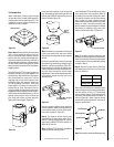
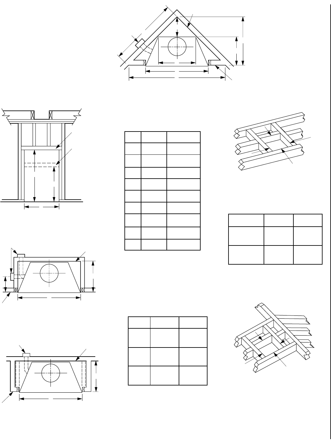
Note: The framed depth, 28
¹³⁄₁₆
" (732mm) from
a framed wall, must always be measured from a
finished surface. If a wall covering such as drywall
is to be attached to the rear wall, then the framed
depth must be measured from the drywall sur-
face. It is important that this dimension be exact.
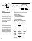
If the appliance is to be elevated above floor level,
a solid continuous platform must be constructed.
The header may rest on the top metal spacers,
but must not be notched to fit around them.
Consult all local codes.
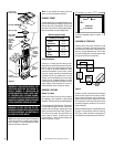
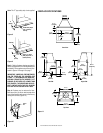
Figure 12
Figure 13
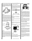
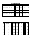
A 48" (1219 mm)
B
1
47 ¹⁄₄" (1200 mm)
B
2
66 ¹⁄₂" (1689 mm)
C 37 ¹⁄₄" (946 mm)
D 18 ⁵⁄₈" (473 mm)
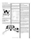
E 94 ⁷⁄₈" (2410 mm)
F 47 ⁷⁄₁₆" (1205 mm)
G 28 ¹³⁄₁₆" (732 mm)
J 17 ¹⁄₂" (445 mm)
K 67" (1702 mm)
Framing Dimensions
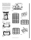
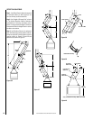
Figure 16
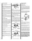
Flue Type A B
FTF10 19" 19"
Vertical (483 mm) (483 mm)
FTF10 30° 19" 29"
Offset (483 mm) (737 mm)
Framing Dimensions for Ceiling
Figure 14
Figure 15
Pitch C D*
0/12 19" 19"
(483 mm) (483 mm)
6/12 19" 22"
(483 mm) (559 mm)
12/12 19" 27"
(483 mm) (686 mm)
*Perpendicular to roof ridge
Figure 17
Framing Dimensions for Roof
A
B
1
B
2
Header
False Header
Fireplace Framing
FOAK-4 Combustion
Air Kit
G
A
J
Outside Chase
Back Wall of Chase/Enclosure
Including Finishing Materials
if any
Rough Framing Face
(Unfinished Shown)
A
E
G
F
D
C
K
FOAK-4
Back Wall of Chase/Enclosure
Including Finishing Materials if any
Rough
Framing Face
(Unfinished Shown)
Corner Installation
A
B
Ceiling Framing
C
D
Roof Framing
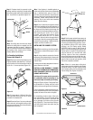
G
A
FOAK-4
Inside Chase
Back Wall of Chase/Enclosure
Including Finishing Materials
if any
Rough Framing Face
(Unfinished Shown)