


4
NOTE: DIAGRAMS & ILLUSTRATIONS ARE NOT TO SCALE.
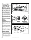
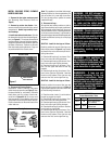
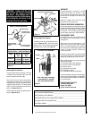
Millivolt Appliances - Appliances with
Millivolt systems will be fitted with the gas
control valve shown in Figure 3.
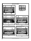
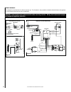
Electronic Appliances - Appliances with
electronic systems will be fitted with the
electronic valve shown in
Figure 4.
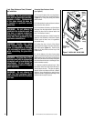
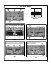
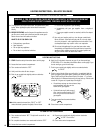
Millivolt Appliances - To light millivolt ap-
pliances refer to
Figure 2. Detailed lighting
instructions are found on
Pages 18 & 19 . Mil-
livolt appliance lighting instructions may also
be found on the pull out lighting instruction
labels attached to the gas control valve.
Once the pilot is lit, the main burner may be
turned ON and OFF using wall switch, remote
control, optional on unit rocker switch (FRS),
or wall thermostat. To operate: Toggle the
switch between its ON and OFF positions.
If your millivolt appliance is equipped with an
optional remote switch kit (wall switch, remote
control, rocker switch, or wall thermostat) and
the pilot is lit, the appliance main burner may be
turned on and off using the optional switch.
Note: To prevent excessive resistance in burner
circuit (which can cause burner operation prob-
lems), only one burner control switch should
be wired to valve.
Electronic Appliances -
To light electronic appliances refer to the detailed
lighting instructions found on
Pages 20 & 21
of these instructions. Electronic appliance
lighting instructions may also be found on the
pull out lighting instruction labels attached to
the gas control valve.
If your electronic appliance is equipped with an
optional remote wall switch or remote control kit
the appliance main burner may be turned on and
off with the wall switch or remote control.
If your electronic appliance is not equipped with
a wall switch or remote control, the main burner
must be turned off and on with a gas control
switch located in some other location by the
installer. Contact the installer for directions.
Variable Flame Height Adjustment
1. All millivolt appliances are equipped with a
variable gas control valve. Flame height for
these models may be adjusted through a
range between fixed low and high settings
while the appliance is in operation. Adjust
the flame height as desired after lighting the
appliance by rotating the variable adjustment
control knob (HI/LO) located on the front of
the valve (refer to Figures 3 & 4 ).
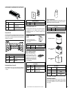
Figure 4
SIT Millivolt Gas Valve
Figure 3
Dexen Electronic Gas Valve
Pilot Stage
Terminal
Pressure-Tap
(Inlet)
Pilot Gas
Outlet
Supply Gas
Inlet
Pressure-Tap
(Manifold)
Burner Stage
Terminal
Ground
(TP)
PILOT
OUT
VENT
LO
TH
TP
TH
TP
HI
IN
IN
Gas Outlet
To Burner
Regulator
Mounting Screw
Variable Flame
Height Adjustment
Manifold Pressure
Port
Inlet
Pressure
Port
Main Gas Control Knob
H
I
L
O
W
TPTH TP TH
P
I
L
O
T
P
I
L
O
T
O
N
it
O
F
F
IN
OUT
Gas Inlet
Terminals TPTH, TP & TH
Gas
Outlet
Figure 2
Gas Flex Line
5 Inch
Pipe Nipple
Valve
Piezo
Spring Door Latch