


NOTE: DIAGRAMS & ILLUSTRATIONS NOT TO SCALE.
18
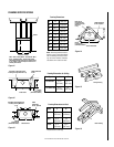
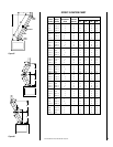
Chimney Section 63L10 FTF8-12
63L13 FTF8-18
63L14 FTF8-36
63L15 FTF8-48
Canadian 62L92 FTF8-18C
Chimney Section 62L93 FTF8-36C
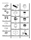
Take Off Boot 91L04 FATO
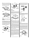
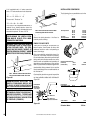
Outside Combustion Air Kits
(with duct) 81L87 FOAK
(without duct) 81L88 FOAK-LD
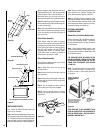
Secure the hearth extension to the floor to
prevent possible shifting.
FINISH TO YOUR TASTE
There are a wide variety of “finished looks” for
these fireplaces, from formal wall decor with
elaborate mantels to rustic wood paneling or
warm brick facings.
Only noncombustible materials like stone, tile,
brick, etc., may overlap the black front facing.
Do not extend these materials beyond the black
facing and into the firebox area. Be sure not to
interfere with the installation and operation of
glass doors or block the upper or lower grilles.
Seal all joints between the black facing and wall
surrounds to prevent air intrusion. Use non-
combustible caulking material only to seal the
black metal facing to the surround material on
the finished wall.
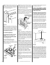
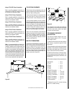
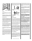
Combustible materials may project beyond the
sides of the fireplace opening as long as they
are kept within the shaded areas illustrated in
Figure 52
.
Figure 51
Figure 52
12"
12"
Min. Distance To
Unprotected Side Wall
8"
45°
Combustible
Materials
Allowed In
Shaded Area
“Safe Zone”
8"
1"
Min. Distance To
Protected Side Wall
Fireplace
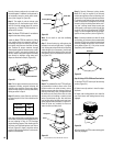
A ³⁄₄" marble slab set in ¹⁄₂" mortar covers the
brick, “R” for the marble and mortar becomes:
“R”
M
= r x T
M
= 0.09 x ³⁄₄" = .068
“R”
M
= r x T
M
= 0.20 x ¹⁄₂" = .10
The sum of all “R values” is:
.70 + .10 +. 068 + .10 = .968
This would be an acceptable combination of
material for the hearth extension since the
total calculated “R value” of the materials used
exceeds the required “R value” of 0.78.
WARNING: THE CRACK BETWEEN THE
FIREPLACE AND THE HEARTH EXTEN-
SION MUST BE SEALED WITH A NON-
COMBUSTIBLE MATERIAL.
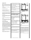
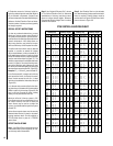
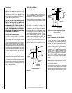
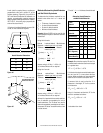
WARNING: WHEN INSTALLING HEARTH
EXTENSION IN FRONT OF A NON-CIRCU-
LATING FIREPLACE MODEL, THE FIRE-
PLACE MUST BE RAISED IF HEIGHT OF
HEARTH EXTENSION EXCEEDS 7" ABOVE
THE BOTTOM OF FIREPLACE (
FIGURE 50
).
WARNING: WHEN INSTALLING THE
HEARTH EXTENSION BE CAREFUL NOT
TO BLOCK THE HEAT-CIRCULATING AIR
INLET GRILL ON CIRCULATING MODELS.
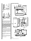
WARNING: WHEN INSTALLING HEARTH
EXTENSION IN FRONT OF A CIRCULAT-
ING FIREPLACE MODEL, THE FIREPLACE
MUST BE RAISED IF HEIGHT OF HEARTH
EXTENSION EXCEEDS 2" ABOVE BOTTOM
OF FIREPLACE (
FIGURE 51
).
Figure 50
5 1/2"
2"
Max. Thickness Of Hearth Extension When
Circulating Models Are On The Floor
Shipping Weight 175 lbs.
INSTALLATION COMPONENTS
The following items are available for use in the
installation of this appliance.
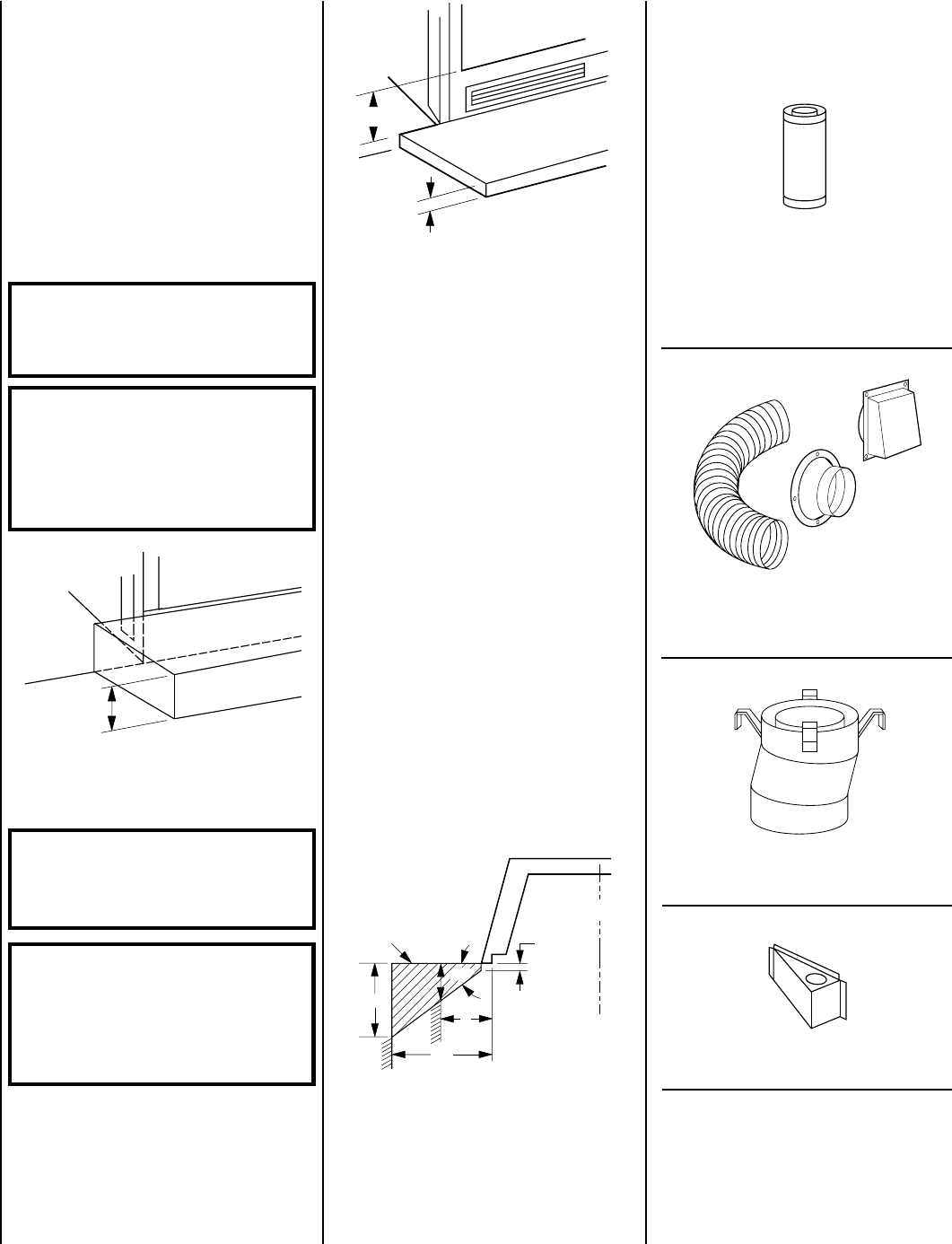
Combination
Offset/Return Elbow 63L28 FTF8-OR15
7"
Max. Thickness Of Hearth Extension When
Non-Circulating Models Are On The Floor