


9
NOTE: DIAGRAMS & ILLUSTRATIONS NOT TO SCALE.
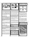
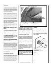
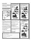
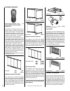
WIRING DIAGRAMS
Wiring diagrams are provided here for refer-
ence purposes only. This information is also
provided on schematics attached directly to
the appliance on a pullout panel located within
the control compartment.
CAUTION: LABEL ALL WIRES PRIOR TO DIS-
CONNECTION WHEN SERVICING CONTROLS.
WIRING ERRORS CAN CAUSE IMPROPER AND
DANGEROUS APPLIANCE OPERATION.
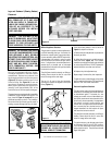
Electronic System Wiring
(Without Forced Air Kit)
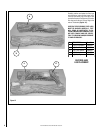
Electronic System Wiring
(With Forced Air Kit)
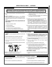
WARRANTY
Your gas appliance is covered by a limited
twenty year warranty. You will find a copy of
the warranty accompanying this manual.
Please read the warranty to be familiar with its
coverage.
Retain this manual. File it with your other
documents for future reference.
Normally, all parts should be ordered through
your distributor or dealer. Parts will be shipped
at prevailing prices at time of order.
If you encounter any problems or have any
questions concerning the installation or appli-
cation of this system, please contact your dis-
tributor, or LHP directly:
LHP
1110 West Taft Avenue
Orange, CA 92865
PRODUCT REFERENCE INFORMATION
We recommend that you record the following
important information about your fireplace.
Please contact your dealer for any questions
or concerns. For the number of your nearest
dealer, please call 800-731-8101
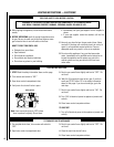
REPLACEMENT PARTS
A complete parts list is found at the end of this
manual. Use only parts supplied from the
manufacturer.
Your Fireplace's Model Number _______________________________________
Your Fireplace's Serial Number ________________________________________
The Date On Which Your Fireplace Was Installed __________________________
The Type of Gas Your Fireplace Uses ___________________________________
Your Dealer's Name_________________________________________________
When ordering repair parts, always give the
following information:
1. The model number of the appliance.
2. The serial number of the appliance.
3. The part number.
4. The description of the part.
5. The quantity required.
6. The installation date of the appliance.
Electronic System Wiring
(Without Forced Air Kit)
Limit
Switch
Thermopile
ON/OFF Wall
Switch
TH
TP
TH
TP
1. If any of the original wire as supplied must be replaced,
1. it must be replaced with Type AWM 105°C – 18 GA. wire.
2. 120V, 60Hz – Less than 3 amps.
LIMIT SW.
ON/OFF SW
GND
Ignitor
Junction Box
Transf.
120 V.
W
BK
Gas Valve
M
C
BL
BK
24 V
MV
TH
TR
GND
PV
IGN
Ignition Control
Factory Wired
Field Wired
P
PV/MV
GND
W
BL
BK
W
GHC/GRD-5500
Robertshaw Ignition Control Equipped
24V
LOW
VOLTAGE
120 VAC
BK
BK
W
GHC Series Only
Green
Ground
Screw
R
BK
R
1. If any of the original wire as supplied must be replaced,
1. it must be replaced with Type AWM 105°C – 18 GA. wire.
2. 120V, 60Hz – Less than 3 amps.
LIMIT SW
ON/OFF SW
GND
W
Ignitor
Junction Box
Transf.
120 V.
W
BK
Gas Valve
M
C
BL
BK
24 V
MV
TH
TR
GND
PV
IGN
Ignition Control
Factory Wired
Field Wired
P
PV/MV
GND
W
BL
BK
W
GHC-5500
Robertshaw Ignition Control Equipped
24V
LOW
VOLTAGE
120 VAC
BK
BK
Opt
Blower
WALL BLOWER SW
BK
Green
Ground
Screw
Appliance
Ground
Screw
R
BK
R
1. If any of the original wire as supplied must be replaced,
1. it must be replaced with Type AWM 105°C – 18 GA. wire.
2. 120V, 60Hz – Less than 3 amps.
LIMIT SW
ON/OFF SW
120 VAC. BK
GND
NEU. W
Ignitor
Junction Box
Transf.
120 V.
W
BK
Gas Valve
M
C
BK
24 V
MV
24V
GND
PV
Ignition Control
Factory Wired
Field Wired
P
PV/MV
G
BL
BK
W
GHC/GRD-5500
(Honeywell Ignition Module Equipped)
24V
Low Voltage
BK
GND
(Burner)
24V
TH-W
(OPT.)
SPARK
W
BL
R
Green
Ground
Screw
BK
R